Netgear M5300-52G3 Hardware Installation Guide - Page 16
Create a Stack, Stack Using SFP+ on the Front Panel
 |
View all Netgear M5300-52G3 manuals
Add to My Manuals
Save this manual to your list of manuals |
Page 16 highlights
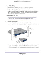
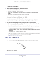
NETGEAR Managed Stackable Switch M5300 Series Create a Stack You can connect up to eight switches to form a stack with a single management IP address. The switches automatically select a master unit. Once the master is selected, you can use its console to manage all the switches in the stack. You can use either the SFP+ ports on the front panel or the IO modules on the rear panel of a switch to create a stack. Stack Using SFP+ on the Front Panel The cabling shown in the stacking procedure has a single loop. You can use additional loops to provide redundancy and allow load balancing. Any SFP+ ports on the front panel can be used for stacking using the following: • Two AXM761/AXM762/AXM63 10G SFP+ modules per switch • Two AXC761/AXC763 Direct Attach SFP+ cables per switch • Two Cat6 RJ45 patch cables per switch Use fiber links between stacked switches in different locations. Different cable types can be used in a stack. For SFP+ ports, use LC optical cables. For RJ45 ports, use Cat6A cables. To set up a stack: 1. Install a 10G SFP+ module (AXM761/762/763) into the SFP+ port at the front of each switch. 2. Connect a fiber cable between a pair of 10G SFP+ modules (AXM761/762/763) modules in each switch in a stack. Connecting switches with AXM modules and stacking cables Hardware Installation 16
-
 1
1 -
2
-
3
-
4
-
5
-
6
-
7
-
8
-
9
-
10
-
 11
11 -
 12
12 -
 13
13 -
 14
14 -
 15
15 -
 16
16 -
 17
17 -
 18
18 -
 19
19 -
 20
20 -
 21
21 -
22
-
23
-
24
-
25
-
26
-
27
-
28
-
29
-
30
-
31
-
32
 |
 |