Netgear WAC510 Installation Guide - Page 1
Netgear WAC510 Manual
 |
View all Netgear WAC510 manuals
Add to My Manuals
Save this manual to your list of manuals |
Page 1 highlights
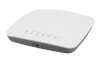
Installation AC WiFi Business Access Point (WAC510) with NETGEAR Insight app for easy management Package Contents Unpack the box and verify the contents: • NETGEAR® AC WiFi Business Access Point (WAC510) • Installation guide • Ceiling and wall installation kit • Mounting installation guide Set Up the Access Point The following table shows the different setup options that are available to you and the requirements for the access point (AP). Setup Option Connect Power Mode Over Source Extra Setup Requirements Information AP to Ethernet PoE Switch WAN port PoE AP mode None See this guide AP to Ethernet non-PoE Switch WAN port Power AP mode Order a power See the user adapter adapter manual AP to DSL or cable WAN port Power Router Internet modem adapter mode Order a power adapter Change to Router mode See the user manual Note: For more information about the various setup options, see the NETGEAR AC WiFi Business Access Point (WAC510) User Manual. Before mounting the access point in a high location, first set up, configure, and test the access point to verify WiFi network connectivity. ¾¾ To set up the access point with a PoE switch: Connect an Ethernet cable from the yellow WAN port on the access point to a Power over Ethernet (PoE) switch. The WAN port on the access point also functions as a PoE port. In this setup, the access point does not require a power adapter. Internet Note: Cable not included. PoE port on a PoE switch WAN port (also PoE port) The following table shows the LED behavior on the access point. LED Power LED Activity LED WAN LED Description •Off. Power is off. •Solid green. Power is on and the access point is ready. •Solid amber. During startup, the Power LED lights solid amber. If after 5 minutes the LED remains solid amber, a boot error occurred. •Fast blinking amber. Firmware update in progress. •Off. No link with the network is detected. •Solid green. A link with the network is detected. •Blinking green. Network traffic is detected. •Off. No Ethernet link is detected. •Solid amber. A 10/100 Mbps Ethernet link is detected. •Solid green. A 1000 Mbps Ethernet link is detected. LAN LED 2.4G WLAN LED 5G WLAN LED •Off. No Ethernet link is detected. •Solid amber. A 10/100 Mbps Ethernet link is detected. •Solid green. A 1000 Mbps Ethernet link is detected. •Off. The 2.4 GHz WiFi radio is off. •Solid green. The 2.4 GHz WiFi radio is on. •Solid blue. One or more WLAN clients are connected to the 2.4 GHz radio. •Blinking blue. WLAN traffic is detected on the 2.4 GHz radio.. •Off. The 5 GHz WiFi radio is off. •Solid green. The 5 GHz WiFi radio is on. •Solid blue. One or more WLAN clients are connected to the 5 GHz radio. •Blinking blue. WLAN traffic is detected on the 5 GHz radio.
-
 1
1 -
 2
2
 |
 |
