Netgear WAC740 Installation Guide - Page 1
Netgear WAC740 Manual
 |
View all Netgear WAC740 manuals
Add to My Manuals
Save this manual to your list of manuals |
Page 1 highlights
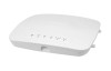
Installation NETGEAR ProSAFE Dual Band Wireless AC Access Point WAC740 Package Contents Unpack the box and verify the contents: • WAC740 ProSAFE Dual Band Wireless AC Access Point • Category 5e Ethernet cable • Installation guide • Ceiling and wall installation kit • Ceiling and wall installation guide Set Up the Access Point Before mounting the access point in a high location, first set up and test the access point to verify WiFi network connectivity. IMPORTANT: You can deploy the WAC740 access point only in a WiFi network that is managed by a ProSAFE wireless controller. ¾¾ To cable the access point: 1. Connect an Ethernet cable from LAN port 1 on the access point to a LAN port on a PoE+ switch, that is, an 802.3at-compatible switch. 2. Connect an Ethernet cable from the PoE+ switch to an Ethernet port on the computer. 3. Check the LEDs to verify that the access point is set up correctly. LED Power LED Activity LED Description •Off. Power is off. •Solid green. Power is on and the access point is ready. •Alternating green and amber. The access point is receiving insufficient PoE power. •Solid amber, then blinking amber, then solid green. During startup, the Power LED lights solid amber for about 30 seconds, turns solid green temporarily, then blinks amber while the configuration is being synchronized and the firmware is being updated, and finally turns solid green. •Blinking amber at moderate speed. The configuration between the access point and the wireless controller is being synchronized. •Blinking amber at fast speed. Firmware is being upgraded. •Off. No link with the network is detected. •Blinking amber at moderate speed. A link with the network is detected. •Blinking green. Network traffic is detected. LED Description LAN LED 1 •Off. No Ethernet link or Ethernet LAG link is detected. •Solid green. A 2.5 Gbps Ethernet link is detected. •Solid amber. A 1 Gbps or 100 Mbps Ethernet link is detected. •Solid green in a LAG. A 1 Gbps Ethernet LAG link is detected. •Solid amber in a LAG. The Ethernet LAG link of LAN port 2 is down. Note: If both LAN LED 1 and LAN LED 2 light solid green, the LAN ports are members of a link aggregation group (LAG) and both LAG links are up. LAN LED 2 •Off. No Ethernet LAG link is detected. •Solid green in a LAG. A 1 Gbps Ethernet LAG link is detected. •Solid amber in a LAG. The Ethernet LAG link of LAN port 1 is down. •Off. The 2.4 GHz WiFi radio is off. •Solid green. The 2.4 GHz WiFi radio is on. 2.4 GHz WLAN LED •Blinking green. WiFi activity is detected on the 2.4 GHz WiFi radio. 5 GHz WLAN LED •Off. The 5 GHz WiFi radio is off. •Solid green. The 5 GHz WiFi radio is on. •Blinking green. WiFi activity is detected on the 5 GHz WiFi radio. The access point uses a DHCP client that is enabled by default. If your network includes a DHCP server, the access point obtains an IP address from the DHCP server. If your network does not include a DHCP server, the access point sets its IP address to a static IP address of 192.168.0.160. If your network includes a DHCP server, note the following: • Make sure that Option 43 is enabled on the DHCP server. • Make sure that the DHCP server specifies the IP address of the wireless controller in the required hexadecimal format in the Option 43 field. For example, if the IP address of the wireless controller is 192.168.0.250, you must enter the hexadecimal string 02:04:C0:A8:0:FA. To compose the address, start with 02:04: and then add each of the four address octets in hexadecimal format, separated by colons. The first two octets (02:04) define a standalone NETGEAR wireless controller, or in a stack, the first wireless controller in the stack.
-
 1
1 -
 2
2
 |
 |
