Netgear XSM4324FS Installation Guide - Page 1
Netgear XSM4324FS Manual
 |
View all Netgear XSM4324FS manuals
Add to My Manuals
Save this manual to your list of manuals |
Page 1 highlights
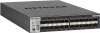
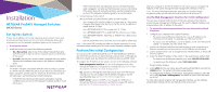
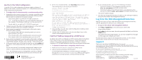
Installation NETGEAR ProSAFE Managed Switches M4300 Series Set Up the Switch Prepare the installation site so that mounting, access, power source, and environmental requirements are met. For more information about these requirements, see the hardware installation guide on the resource CD. ¾¾ To set up the switch: 1. Install the switch using one of the following methods: • On a flat surface. Attach one of the rubber footpads that came with the switch on each of the four concave spaces on the bottom of the switch. • In a rack. Use the rack-mount kit that is supplied with your switch, following the installation instructions in the hardware installation guide. 2. Apply AC power. The Power LED lights solid yellow while the switch conducts a poweron self-test (POST). After the switch passes the POST, the Power LED lights solid green, and the switch is functional. If the Power LED does not light green, see the following troubleshooting tips: • If the POST fails, the Power LED remains solid yellow. See the troubleshooting section of the hardware installation guide for more information. • If the Power LED does not light at all, check to see that the power cable is plugged in correctly and that the power source is functioning. If this action does not resolve the problem, see the troubleshooting section of the hardware installation guide for more information. 3. Connect devices to the switch. We recommend using the following cables and SFP modules: • Use a Category 5e (Cat 5e) cable for a copper port at 1 Gbps and a Category 5e or better (Cat 5e, Cat 6, Cat 6a, or Cat 7) cable for a copper port at 10 Gbps. • Use a NETGEAR AGM734 for a copper port at 1 Gbps. • Use a NETGEAR AGM731F or AGM732F for a fiber port at 1 Gbps. • Use a NETGEAR AXM761, AXM762, or AXM764 for a fiber port at 10 Gbps. • Use a NETGEAR AXC761 (1 m) or AXC763 (3 m) cable for a fiber port. Note: If purchased, SFP modules and cables are shipped separately. For more information about installing an SFP module, see the hardware installation guide. Perform the Initial Configuration You can access the switch through the out-of-band (OOB) port (which is also referred to as the service port), through a console port, or through any Ethernet network port. By default, the switch functions as a DHCP client. To configure the IP address of the switch, use one of the following methods: • Web management interface. Use the web management interface through the OOB port or any Ethernet network port (see Use the Web Management Interface for Initial Configuration). • CLI. Use the CLI through the mini USB console port or RJ-45 RS232 console port. You can configure the IP address manually or use the ezconfig utility (see Use the CLI for Initial Configuration). • DHCP server. Connect a DHCP server through the OOB port or through any Ethernet network port and find the assigned IP address (see Find the IP Address Assigned by a DHCP Server). After you configure or find the IP address of the switch, you can configure the features of the switch through the web management interface or the CLI. Note: For more information about the tasks that are described in this installation guide, see the software setup manual on the resource CD. Use the Web Management Interface for Initial Configuration You can use a computer that functions in the same subnet as the switch to access the web management interface over the switch's default IP address and assign another static IP address to the switch. ¾¾ To access the web management interface over the switch's default IP address: 1. Configure your computer with a static IP address: • For access over an Ethernet network port, use an IP address in the 169.254.0.0/16 subnet. For example, use 169.254.100.201. • For access over the OOB port, use an IP address in the 192.168.0.0/16 subnet. For example, use 192.168.0.100. 2. Connect an Ethernet cable from an Ethernet port on your computer to an Ethernet network port on the switch or to the OOB port on the switch. 3. Launch a web browser such as Google Chrome, Mozilla Firefox, or Microsoft Internet Explorer. 4. Enter the default IP address of the switch in the web browser address field: • For access over an Ethernet network port, enter 169.254.100.100. • For access over the OOB port, enter 192.168.0.239. A login window displays. 5. Enter admin for the user name, leave the password field blank, and click the LOGIN button. The System Information page displays. 6. To configure the IP address of the switch, management interface, and OOB port, select System > Management, and select an option from the menu on the left. For information about using the web management interface, see the software administration manual and the user manual on the resource CD.
-
 1
1 -
 2
2
 |
 |