NordicTrack Cx 1600 Elliptical English Manual - Page 9
the Handlebar Leg
 |
View all NordicTrack Cx 1600 Elliptical manuals
Add to My Manuals
Save this manual to your list of manuals |
Page 9 highlights
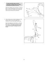
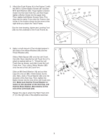
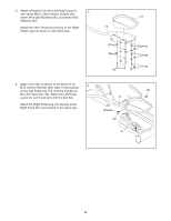
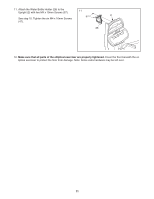
7. Identify the Left Handlebar (19), which is marked 7 with an "L." Insert the Left Handlebar into one of the Handlebar Legs (17). Next, turn the Left Handlebar and the Handlebar Leg so that the wide side of the pivot tube on the Left Handlebar is above the hexagonal holes in the Handlebar Leg. Attach the Left Handlebar with two M8 x 38mm Button Bolts (58) and two M8 Nylon Locknuts (72). Make sure that the Nylon Locknuts are inside of the hexagonal holes. Do not tighten the Button Bolts yet. Assemble the Right Handlebar (20) and the other Handlebar Leg (17) in the same way. 19 20 Wide side of pivot tube 58 72 58 Hexagonal Holes 17 17 8. Apply a small amount of grease to the sides of two Wave Washers (88) and two Thrust Washers (66). Slide the Left Handlebar (19) onto the Handlebar Axle (16) as shown. Next, slide a Wave Washer (88) onto the end of the Handlebar Axle. Slide an M8 Small Washer (18) and an Axle Cap (41) onto an M8 x 19mm Button Screw (56). Next, slide a Thrust Washer (66) onto the shoulder of the Axle Cap. Then, tighten the Button Screw into the end of the Handlebar Axle (16). Make sure that the Thrust Washer remains on the shoulder of the Axle Cap, and that the Wave Washer (88) remains on the end of the Handlebar Axle. Assemble the Right Handlebar (20) in the same way. Then, tighten both M8 x 19mm Button Screws (56) at the same time. 8 19 16 66 88 18 Grease 56 41 9 20 66 56 18 41 88 1
-
 1
1 -
2
-
3
-
 4
4 -
 5
5 -
 6
6 -
 7
7 -
 8
8 -
 9
9 -
 10
10 -
 11
11 -
 12
12 -
 13
13 -
 14
14 -
15
-
16
-
17
-
18
-
19
-
20
-
21
-
22
-
23
-
24
-
25
-
26
-
27
-
28
 |
 |
