NordicTrack E3200 Treadmill Uk Manual - Page 8
Short Console Bolts into the Uprights.
 |
View all NordicTrack E3200 Treadmill manuals
Add to My Manuals
Save this manual to your list of manuals |
Page 8 highlights
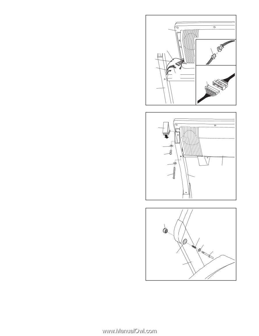
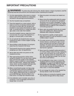
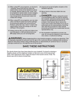
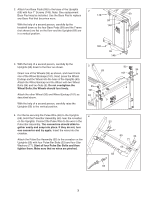
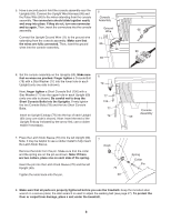
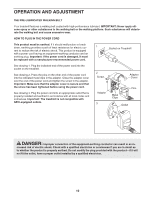
5. Have a second person hold the console assembly near the 5 Uprights (69). Connect the Upright Wire Harness (98) and the Pulse Wire (66) to the wires extending from the console Console assembly. The connectors should slide together easily Assembly and snap into place. If they do not, turn one connector and try again. Then, insert the connectors into the console assembly. Ground Wire 66 Connect the Upright Ground Wire (11) to the ground wire 11 extending from the console assembly. Make sure that the wires are fully connected. Then, insert the ground 66 wires into the console assembly. 98 98 69 6. Set the console assembly on the Uprights (69). Make sure that no wires are pinched. Finger tighten a Console Bolt (78) with a Star Washer (77) into the lower hole in each Upright (only one side is shown). Next, finger tighten a Short Console Bolt (106) with a Star Washer (77) into the upper hole in each Upright (69) (only one side is shown). Be careful not to drop the Short Console Bolts into the Uprights. Firmly tighten the two Console Bolts (78) and the two Short Console Bolts. Insert an Upright Endcap (79) into the top of each Upright (69) (only one side is shown). Note: Insert the end of the Upright Endcap indicated by the arrow first; use a rubber mallet if necessary. 6 79 77 106 77 78 Console Assembly 69 7. Press the Latch Knob Sleeve (70) into the left Upright (69). Note: It may be helpful to use a rubber mallet to fully insert the Latch Knob Sleeve. Remove the knob from the pin. Make sure that the collar and the spring are on the pin as shown. Note: If there are two collars, place one on each side of the spring. Insert the pin into the Latch Knob Sleeve (70) and the left Upright (69). Tighten the knob back onto the pin. 7 Knob 70 69 Spring Collar Pin 8. Make sure that all parts are properly tightened before you use the treadmill. Keep the included allen wrench in a secure place; the allen wrench is used to adjust the walking belt (see page 27). To protect the floor or carpet from damage, place a mat under the treadmill. 8
-
 1
1 -
2
-
 3
3 -
 4
4 -
 5
5 -
 6
6 -
 7
7 -
 8
8 -
 9
9 -
 10
10 -
 11
11 -
 12
12 -
 13
13 -
14
-
15
-
16
-
17
-
18
-
19
-
20
-
21
-
22
-
23
-
24
-
25
-
26
-
27
-
28
-
29
-
30
-
31
-
32
-
33
-
34
 |
 |