NordicTrack Incline Trainer X5 English Manual - Page 10
ceiver included with the chest pulse sensor.
 |
View all NordicTrack Incline Trainer X5 manuals
Add to My Manuals
Save this manual to your list of manuals |
Page 10 highlights
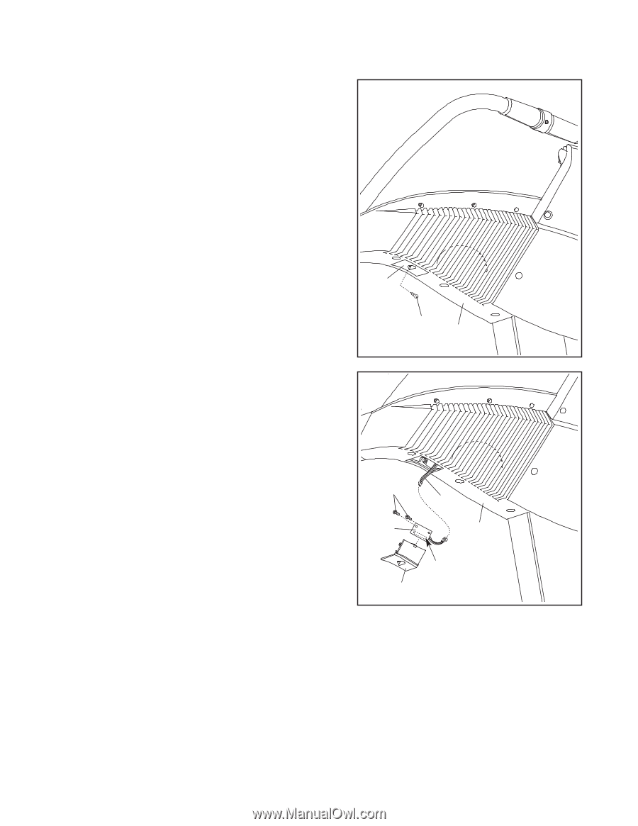
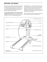
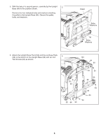
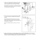
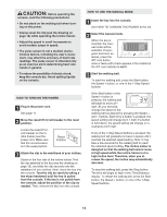
If you purchase the optional chest pulse sensor (see page 27), follow the steps below to install the receiver included with the chest pulse sensor. 1. Make sure that the power cord is unplugged. 1 Look under the Console Back (70) and locate the Access Door (135) on the indicated side of the incline trainer. Remove the Access Door Screw (72) and the Access Door. 135 72 70 2. Connect the wire on the receiver (A) to the indicated wire extending from the console. Hold the receiver so the small cylinder is oriented as shown and is facing the console. Attach the receiver to the plastic posts on the Access Door (135) with the two included small screws. 3. See step 1 on page 9. Make sure that no wires are pinched, and reattach the Access Door (135) to the Console Back (70) with the Access Door Screw (72). Discard the other wires included with the receiver. 2, 3 Small Screws A Wire 70 Small Cylinder 135 10
-
 1
1 -
2
-
3
-
4
-
 5
5 -
 6
6 -
 7
7 -
 8
8 -
 9
9 -
 10
10 -
 11
11 -
 12
12 -
 13
13 -
 14
14 -
 15
15 -
16
-
17
-
18
-
19
-
20
-
21
-
22
-
23
-
24
-
25
-
26
-
27
-
28
-
29
-
30
-
31
-
32
-
33
-
34
-
35
-
36
-
37
-
38
 |
 |