Oki B8300n Guide: Installation B8300 - Page 4
B83LT Installation Manual - oki
 |
View all Oki B8300n manuals
Add to My Manuals
Save this manual to your list of manuals |
Page 4 highlights
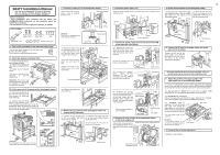
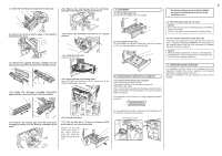
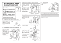
B83LT Installation Manual FOR USE WITH COMPATIBLE OKI DIGITAL PRINTERS. SEE OKI DIGITAL PRINTER SERVICE MANUAL OR INSTALLATION MANUAL TO DETERMINE SUITABILITY. • Start installation after checking that the DATA and COMMUNICATION indicators on the operation panel are neither lit nor blinking. • For installation, a power supply unit is needed. Front mounting plates: 2 pcs. Rear mounting plates: 2 pcs. Screws (M4x8): 4 pcs. Left adjuster: 1 pc. Adjuster covers: 4 pcs. Left paper guides: 2 pcs. Right paper guides: 2 pcs. 1. Turn off the main switch of the main unit of the printer. Turn the main switch located on the front side of the printer to the "OFF" position. Then remove the power plug from the outlet. "OFF" 2. Attach the adjusters and adjust them. Insert the left adjusters to 3 the stand/paper drawer. Turn each adjuster to lower it until it touches the floor. Attach the four adjuster covers. 3 Be sure to attach the left adjuster to prevent overturning. [Caution] The lower tray 2 cannot be pulled out unless the adjuster is lowered to the specified position. 1 3 2 2 3 2 3. Put the main unit of the printer on the stand/paper drawer. Pull out the paper tray of the main unit until it stops and then remove it by lifting both ends of the tray. Hold the main unit of the printer at the positions shown in the illustration and put the main unit on the stand/paper drawer so that the front side and the left side of the main unit are aligned to those of the stand/paper drawer. Front side Rear side [Caution] For installation of the main unit, it must be held by two persons and installed carefully. 4. Connect the main unit to the stand/paper drawer. Attach the two rear mounting plates using a supplied screw for each. Rear mounting plate Rear mounting plate Stand frame [Caution] Insert the rear mounting plates under the Stand frame. Pull out the upper tray of the stand/paper drawer until it stops, and attach the two front mounting plates using a supplied screw for each. Then, remove the lock of the paper tray and close the tray. Front mounting plate Screw Rear mounting plate Screw Front mounting plate Screw Screw Reattach the paper tray of the main unit. 5. Remove the rear cabinet of the stand/paper drawer and remove the AC inlet cover. Remove the four screws that Remove the screw that fixes the fix the rear cabinet and then AC inlet cover and then remove the remove the rear cabinet. AC inlet cover. Cut out the AC inlet cover as shown in the illustration. Rear cabinet Cut out. AC inlet cover 6. Attach the power supply unit. Attach the power supply unit to the brackets and secure it using the three supplied screws. Bracket Bracket Screws Screws Power supply unit 7. Connect the power supply unit harness to the PCU PWB of the main unit of the printer. Remove the screw that fixes the harness cover of the main unit of the printer and slide the harness cover up to remove it. Screw Cut out the harness cover as Cut out. shown in the illustration. Connect the optional power supply harness connector to CN11 (red connector) of the PCU PWB of the main unit of the printer. CN11 Harness cover Connector Reattach the harness cover to its original position and fix it with the removed screw. At this time, ensure that the optional power supply harness are arranged as shown in the illustration. Optional power supply harness Screw • Fix the harness securely to the wire saddle. Wire saddle Harness cover Wire saddle 8. Connect the relay harness of the stand/paper drawer to the power supply unit. Connect the relay harness of the stand/paper drawer to the connector of the power supply unit. Connector of the power supply connector Relay harness of the stand/paper drawer 9. Attach the rear cabinet of the stand/paper drawer. Pass the cord of the power supply unit through the hole of the rear cabinet and attach the rear cabinet to the stand/paper drawer. Attach the AC inlet cover to the rear cabinet of the stand/paper drawer and fix it with the removed screw. Rear cabinet AC inlet cover Screw 3 10. Connect the AC cord of the power supply unit to the main unit of the printer. Connect the AC cord of the power supply unit to the inlet connector of the main unit of the printer at the location shown in the illustration. AC cord 11. Attach the paper guides to the lower tray. Remove the four screws for packing. (See the right illustration.) Insert the left paper guides and right paper guides to the front and rear guide slots for the paper size to be used. (See the illustration below.) (For the AB system, set the guides to A4. For the inch system, set the guides to LT.) Left paper guides Right paper guides Paper guide * If another peripheral device must be installed, carry out the following step at the end of the installation work. 12. Adjust the position of the paper guides of the upper paper tray of the stand/paper drawer. To use the setting mode, insert the power plug of the main unit of the printer to the outlet and turn the main switch on while pressing the [MENU] key and the [OK] key of the operation panel of the main unit of the printer. Press the [MENU] key several times to display "SIZE ADJUSTMENT A" and press the [OK] key. "MAXIMUM SIZE" is displayed. Pull out the paper tray and extend the paper guides to the maximum. Then, return the paper tray into the unit and press the [OK] key. "MINIMUM SIZE" is displayed. Pull out the paper tray again and narrow the paper guides to the minimum. Then, return the paper tray into the unit and press the [OK] key. Rear guide (The rear guide need not be adjusted.) [Caution] If the setting above is not carried out, the paper detection function will not operate. Paper guides 13. Carry out the off center adjustment. Installation is now complete.
-
 1
1 -
 2
2 -
 3
3 -
 4
4 -
 5
5 -
 6
6 -
 7
7 -
 8
8 -
 9
9 -
 10
10 -
11
-
12
-
13
-
14
-
15
-
16
 |
 |
