Oki GL408e GL408e/GL412e Real Time Clock Guide - Page 5
GL4xxe Real-Time Clock Installation
 |
View all Oki GL408e manuals
Add to My Manuals
Save this manual to your list of manuals |
Page 5 highlights
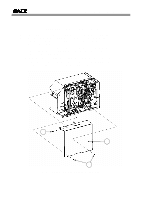
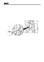
Real-Time Clock Installation Guide GL4xxe Real-Time Clock Installation Before installing the Real-Time Clock chip, make sure the printer is OFF and disconnected from the power supply. Make sure you have discharged any static electricity (by touching a grounded component on the printer). Remove all interface cards prior to removing the rear side cover. 1. Use a Phillips head screwdriver to remove the three screws (1) that secure the left-hand side cover [labelled (2) in the illustration below] that protects the electronics of the printer. 2. Slide the side cover leftward and upward, as shown by the line marked (a). 3. Once the cover has been removed, locate the area circled in RED. There is an empty socket for mounting the Real-Time-Clock chip. (a) 1 2 1 Figure 1. Removing the Left-Side Cover of the printer 5
-
 1
1 -
 2
2 -
 3
3 -
 4
4 -
 5
5 -
 6
6 -
 7
7 -
 8
8
 |
 |
