Onkyo TXSR603B Owner Manual - Page 11
Rear Panel - tx sr603x receiver
 |
UPC - 751398006845
View all Onkyo TXSR603B manuals
Add to My Manuals
Save this manual to your list of manuals |
Page 11 highlights
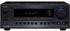
Front & Rear Panels-Continued Rear Panel TX-SR603X 1B CD 5 6 G H 9JK L IR IN DIGITAL COAXIAL IN 1 IN 2 OPTICAL IN 1 12 V TRIGGER OUT ZONE 2 COMPONENT VIDEO IN 3 IN 2 IN 1 OUT Y PB AV RECEIVER MODEL NO. TX-SR 603X ANTENNA AM VIDEO 3 VIDEO 2 FM 75 VIDEO 1 PR IN 2 ZONE 2 SPEAKERS MONITOR DVD OUT V L R S IN OUT IN OUT IN IN ZONE 2 IN 3 LINEOUT IN OUT IN IN OUT IN OUT IN FRONT SURROUND CENTER L L OUT REMOTE CONTROL R CD TAPE VIDEO 3 VIDEO 2 VIDEO 1 R DVD SUB WOOFER SURROUND BACK SPEAKERS L R PRE OUT SUB WOOFER SURROUND SPEAKERS FRONT SPEAKERS L R CENTER SPEAKER M NOPQ R S T U V The page numbers in parentheses show where you can find the main explanation for each item. A OPTICAL DIGITAL The optical digital audio inputs can be used to connect CD and DVD players, and other components with an optical digital audio output. The optical output can be used connect a CD recorder or other digital recorder with an optical digital input. B COAXIAL DIGITAL The coaxial digital audio inputs can be used to connect CD and DVD players, and other components with a coaxial digital audio output. C IR IN (77) If you want to use the remote controller to control the AV receiver from Zone 2, or if the AV receiver is installed in a cabinet and the line of sight between the AV receiver and the remote controller is obstructed, a commercially available IR receiver can be connected here. D 12V TRIGGER OUT ZONE 2 (77) This output can be connected to the 12-volt trigger input on a power amplifier in Zone 2. When Zone 2 is turned on, a 12-volt trigger signal is output. G AM ANTENNA (23) These push terminals are for connecting an AM antenna. H FM ANTENNA (23) This jack is for connecting an FM antenna. I MONITOR OUT The S-Video or composite video jack should be connected to a video input on your TV or projector. J XM ANTENNA This jack is for connecting an XM antenna, sold separately (see page 55). K ZONE 2 SPEAKERS (74) These terminals are for connecting speakers in Zone 2. L FRONT, CENTER, SURROUND & SURROUND BACK SPEAKERS (22) These terminal posts are for connecting your front, center, surround, and surround back speakers. See pages 26-36 for connection information. E COMPONENT VIDEO IN 1, 2, 3 These component video inputs can be used to connect AV components with component video outputs, such as DVD players. F COMPONENT VIDEO OUT This component video output can be used to connect a TV or projector with a component video input. 11
-
 1
1 -
2
-
3
-
4
-
5
-
 6
6 -
 7
7 -
 8
8 -
 9
9 -
 10
10 -
 11
11 -
 12
12 -
 13
13 -
 14
14 -
 15
15 -
 16
16 -
17
-
18
-
19
-
20
-
21
-
22
-
23
-
24
-
25
-
26
-
27
-
28
-
29
-
30
-
31
-
32
-
33
-
34
-
35
-
36
-
37
-
38
-
39
-
40
-
41
-
42
-
43
-
44
-
45
-
46
-
47
-
48
-
49
-
50
-
51
-
52
-
53
-
54
-
55
-
56
-
57
-
58
-
59
-
60
-
61
-
62
-
63
-
64
-
65
-
66
-
67
-
68
-
69
-
70
-
71
-
72
-
73
-
74
-
75
-
76
-
77
-
78
-
79
-
80
-
81
-
82
-
83
-
84
-
85
-
86
-
87
-
88
 |
 |
