Optoma HD20 User's Manual - Page 9
Input / Output Connections - won t turn on
 |
UPC - 796435811037
View all Optoma HD20 manuals
Add to My Manuals
Save this manual to your list of manuals |
Page 9 highlights
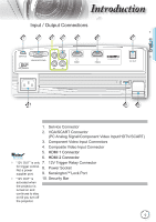
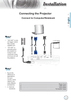
ntroduction Input / Output Connections 1 2 3 4 5 6 7 SERVICE VGA/SCART/YPbPr Y VIDEO Pb Pr HDMI 1 HDMI 2 12V OUT English 8 9 10 1. Service Connector 2. VGA/SCART Connector (PC Analog Signal/Component Video Input/HDTV/SCART) 3. Component Video Input Connectors 4. Composite Video Input Connector Noottee 5. HDMI 1 Connector 6. HDMI 2 Connector "12V OUT" is only 7. 12V Trigger Relay Connector for trigger control. Not a power 8. Power Socket supplier port. 9. KensingtonTM Lock Port "12V OUT" is 10. Security Bar activated when the projector is turned on and continues to stay on till you turn off the projector. 9
-
 1
1 -
2
-
3
-
 4
4 -
 5
5 -
 6
6 -
 7
7 -
 8
8 -
 9
9 -
 10
10 -
 11
11 -
 12
12 -
 13
13 -
 14
14 -
15
-
16
-
17
-
18
-
19
-
20
-
21
-
22
-
23
-
24
-
25
-
26
-
27
-
28
-
29
-
30
-
31
-
32
-
33
-
34
-
35
-
36
-
37
-
38
-
39
-
40
-
41
-
42
-
43
-
44
-
45
-
46
-
47
-
48
-
49
-
50
 |
 |

9
English
Introduction
Input / Output Connections
1. Service Connector
2. VGA/SCART Connector
(PC Analog Signal/Component Video Input/HDTV/SCART)
3. Component Video Input Connectors
4. Composite Video Input Connector
5.
HDMI 1 Connector
6.
HDMI 2 Connector
7. 12V Trigger Relay Connector
8. Power Socket
9. Kensington
TM
Lock Port
10. Security Bar
SERVICE
VGA/SCART/YPbPr
Y
VIDEO
Pb
Pr
HDMI 1
HDMI 2
12V OUT
5
7
4
2
1
6
8
10
9
3
“12V OUT” is only
for trigger control.
Not a power
supplier port.
“12V OUT” is
activated when
the projector is
turned on and
continues to stay
on till you turn off
the projector.
N
ote
N
ote