Oreck XL2635RH Owners Guide - Page 4
To Replace Filter, Dust Bag, Assembly
 |
View all Oreck XL2635RH manuals
Add to My Manuals
Save this manual to your list of manuals |
Page 4 highlights
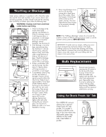
Assembly To assist you in identifying components of your vacuum, the parts have been numbered as follows: 1 Handle tube, upper 2 Tube, lower 3 Power head 4 Outer bag 5 Paper filter dust bag 5 6 Power cord 7 Retaining spring 8 Bag tension bar 9 Zip fastener 10 On/off switch 11 Cord hook 12 Plastic loop/cable clamp 13 Connector assembly 14 Fan housing 15 Cord assembly 16 Cord Strain Relief Assembly 10 9 4 87 3 11 12 1 16 13 2 6 15 14 1 2 TAB 3 Before assembling appliance, remove two screws from connector assembly. Remove cardboard insert by pulling upward (fig 1). With ON/OFF switch facing the front of the unit, slide upper handle tube over matching section of the connector assembly. Hold tab of cord strain relief flush with TOP hole in connector assembly. Insert screw through hole in tab of cord strain relief and firmly tighten to connector assembly. Insert remaining screw in bottom hole of connector assembly and tighten firmly (fig 2). NOTE: The power cord comes installed in the cord strain relief. Should the power cord come loose, simply pinch the power cord together and slide approximately 1 - 2 inches through hole in cord strain relief. Carefully slide power cord over clamp on the cord strain relief and pull excess until the power cord is tightly rested under clamp. Attach cord to cord clip by pressing cord above and below clip ensuring the cord is fully rested in clip (fig 3). 4 To Replace Filter Dust Bag WARNING: Unplug cord from electrical outlet before servicing. BAG REMOVAL: 1. Unsnap bag door from base. 2. Gently pull bag from cardboard collar upwards. BAG INSTALLATION: 1. Slide the cardboard collar completely onto bag dock door. ENFONCEZ JUSQU'À ENTENDRE UN BRUIT PRESIONE HASTA ESCUCHAR UN CHASQUIDO DE SUJECIÓN 2. Firmly push bag dock door with both thumbs on indication point until it snaps.
-
 1
1 -
 2
2 -
 3
3 -
 4
4 -
 5
5 -
 6
6 -
 7
7 -
 8
8
 |
 |
