Panasonic 19 Touchscreen PC version Service Manual - Page 47
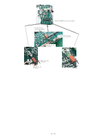
Setting the Power SW PCB
 |
UPC - 092281896069
View all Panasonic 19 Touchscreen PC version manuals
Add to My Manuals
Save this manual to your list of manuals |
Page 47 highlights
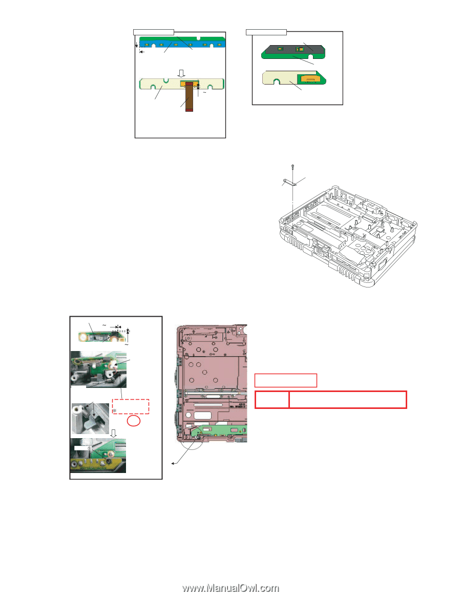
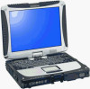
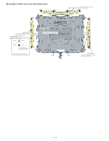
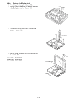
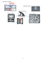
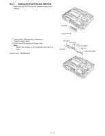
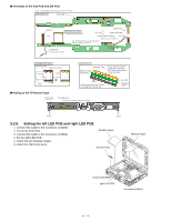
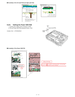
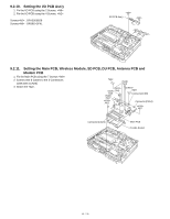
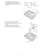
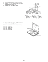
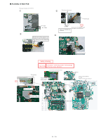
■ Assembly of the left LED PCB and right LED PCB LED(L) PCB Ass'y LED PCB(L) LED Light Guide Sheet(L) Match the edge and attach it. Avoid running over the LED. Back side 0 3mm LED PCB Tape(L) LED(L) FPC Match the edge and attach it. Ensure it does not come over the end of the Board by 0.5 mm or more. Avoid coming over it. 9.2.9. Setting the Power SW PCB 1. Connect the Cable to the Connector. (CN9) 2. Fix the Power SW PCB using the Screw. Screws : DFHE5025XA LED(R) PCB Ass'y Match the edge and attach it. LED Light Guide Sheet(R) LED PCB(R) LED PWB Tape(R) Match the edge and attach it. Connector(CN9) Power SW PCB ■ Assembly of the Power SW PCB (Note) Arrow without specified measurement: 0 to 0.5 mm Power SW PCB 0 1mm Power Spring Sheet 0 1mm Attach Insert Spring Insert it to Knob and Pin on the Top Case Insert the Cushion between the ribs. Avoid coming over S2 Screw Fold the board back and fix with screw. Safety Working CAUTION S1:Insulation S2:Pinching Cables S4:Part No. Check S5:Others S3:Sharp Edge
-
 1
1 -
2
-
3
-
4
-
5
-
6
-
7
-
8
-
9
-
10
-
11
-
12
-
13
-
14
-
15
-
16
-
17
-
18
-
19
-
20
-
21
-
22
-
23
-
24
-
25
-
26
-
27
-
28
-
29
-
30
-
31
-
32
-
33
-
34
-
35
-
36
-
37
-
38
-
39
-
40
-
41
-
 42
42 -
 43
43 -
 44
44 -
 45
45 -
 46
46 -
 47
47 -
 48
48 -
 49
49 -
 50
50 -
 51
51 -
 52
52 -
53
-
54
-
55
-
56
-
57
-
58
-
59
-
60
-
61
-
62
-
63
-
64
-
65
-
66
-
67
-
68
-
69
-
70
-
71
-
72
-
73
-
74
-
75
-
76
-
77
-
78
-
79
-
80
-
81
-
82
-
83
-
84
-
85
-
86
-
87
-
88
-
89
-
90
 |
 |