Panasonic AJ-HPM200 Operating Instructions - Page 43
Recording HD SDI Signals Output by an HD Camera as 1080/23.98p, Variable Frame Rate-Recording
 |
View all Panasonic AJ-HPM200 manuals
Add to My Manuals
Save this manual to your list of manuals |
Page 43 highlights
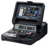
Introduction Variable Frame Rate-Recording To record active frames from the output of a variable framerate camera, set setup menu No. 040 (VFR REC) to ON. This enables instant viewing of slow-motion and fast-motion speed effects during shooting. ◆ NOTE: • Audio and external time codes cannot be recorded in this mode. • The P2 card that is being recorded cannot be changed during recording. • In this mode, the remaining P2 card capacity at 60p (50p), the slowest slow-speed effect, is indicated. • When 59-23 or 60-24 is set in setup menu No. 25 (SYSTEM FREQ), movement in HD SDI video output may look unnatural when the input frame rate is something other than 24p. • Changing the frame rate while recording a video signal from a variable frame rate camera may result in frame loss in the changeover phase. Recording HD SDI Signals Output by an HD Camera as 1080/23.98p The unit is capable of AVC-Intra 1080/23.98p native recording of HD SDI (1080/23.98p over 59.94i) output from an HD camera. 2 Make the following setup menu settings. Item Setting Recording HD SDI signals from camera output 1 Connect the HD SDI (1080/23.98p over 59.94i) output from an HD camera recorder to the SDI IN connector and press the INPUT SELECT button to select HD SDI. No.25 No.020 SYSTEM FREQ SYS FORMAT 59-23 1080p 3 Hold down the REC button and the STILL/PAUSE button simultaneously to set the unit to REC PAUSE mode. 4 To start recording, press the STILL/PAUSE button while viewing the video output from the camera HD SDI output. HD SDI (1080/23.98p over 59.94i) output SDI IN connector VIDEO REF VIDEO IN TIME CODE AUDIO MON IN IN L AES/EBU IN IN SDI 75 IN AUTO OUT R E CH1·2 CH3·4 M O T E OUT R OUT OUT OUT DVCPRO/DV 1 3 4 POWER ON OFF METER FULL/FINE PLAYER MONITOR SELECT METER SELECT CH 1-4 CH 5-8 SOURCE SELECT COUNTER RESET INPUT SELECT VIDEO AUDIO NEW TC PRESET REC VAR UNITY CH 1 CH 2 CH 3 CH 4 PROP TEXT MEMO INT REGEN TCG PRESET MARKER EXT THUMBNAIL PLAYLIST VIDEO A1 A2 GO TO STOP PREVIEW REC A.LEVEL REC STILL/ PLAY PAUSE REW FF REVIEW 1 CLIP PLAY PREV NEXT EDIT MODE A3 A4 A.DUB SET LAST X TRIM MODE EXIT MULTI SEL MENU DELETE SLOT SELECT IN ENTRY OUT CANCEL/PF DIAG SLOT CLIP OPERATION PF1 CLIP LIST PF2 ALL CLIP PF3 SHIFT PF4 ◆ NOTE: • Setup menu No. 155 (AUTO REC) to TYPE2 and set the CONTROL switch to REMOTE. The unit will then automatically start and stop recording as the REC and STOP buttons are pressed on the camera. • SDI is output in the 1080/23.98 PsF video format. IEEE1394 is not output. • No time code can be input to the TIME CODE IN connector. • The SDI output is delayed relative to LCD monitor and monitor video output. Analog audio, speaker and headphone output is synchronized to the LCD monitor and monitor video output. To synchronize these outputs to SDI output, set setup menu No. 778 (AUD OUT DLY) to ON. • Set camera TCG to FREE RUN. A TC/UB of an SDI input that cannot be properly read cannot be normally recorded. 43 Introduction: Recording From a Variable Frame-Rate Camera
-
 1
1 -
2
-
3
-
4
-
5
-
6
-
7
-
8
-
9
-
10
-
11
-
12
-
13
-
14
-
15
-
16
-
17
-
18
-
19
-
20
-
21
-
22
-
23
-
24
-
25
-
26
-
27
-
28
-
29
-
30
-
31
-
32
-
33
-
34
-
35
-
36
-
37
-
 38
38 -
 39
39 -
 40
40 -
 41
41 -
 42
42 -
 43
43 -
 44
44 -
 45
45 -
 46
46 -
 47
47 -
 48
48 -
49
-
50
-
51
-
52
-
53
-
54
-
55
-
56
-
57
-
58
-
59
-
60
-
61
-
62
-
63
-
64
-
65
-
66
-
67
-
68
-
69
-
70
-
71
-
72
-
73
-
74
-
75
-
76
-
77
-
78
-
79
-
80
-
81
-
82
-
83
-
84
-
85
-
86
-
87
-
88
-
89
-
90
-
91
-
92
-
93
-
94
-
95
-
96
-
97
-
98
-
99
-
100
-
101
-
102
-
103
-
104
-
105
-
106
-
107
-
108
-
109
-
110
-
111
-
112
-
113
-
114
-
115
-
116
-
117
-
118
-
119
-
120
-
121
-
122
-
123
-
124
-
125
-
126
-
127
-
128
-
129
-
130
-
131
-
132
-
133
-
134
-
135
-
136
-
137
-
138
-
139
-
140
-
141
-
142
-
143
-
144
-
145
-
146
-
147
-
148
-
149
-
150
-
151
-
152
-
153
-
154
-
155
-
156
-
157
-
158
-
159
-
160
-
161
-
162
-
163
-
164
-
165
-
166
-
167
-
168
-
169
-
170
-
171
-
172
-
173
-
174
-
175
-
176
-
177
-
178
-
179
-
180
-
181
-
182
-
183
-
184
-
185
-
186
-
187
-
188
-
189
-
190
-
191
-
192
-
193
-
194
-
195
-
196
-
197
-
198
-
199
-
200
-
201
-
202
-
203
-
204
-
205
-
206
-
207
-
208
-
209
-
210
-
211
-
212
-
213
-
214
-
215
-
216
-
217
-
218
 |
 |
