Panasonic BB-HCM581A-W Installation Guide - Page 3
Connecting External Sensors, Connecting a Video Device BB-HCM580A Only, Connecting Audio/video - bb network camera
 |
UPC - 037988845385
View all Panasonic BB-HCM581A-W manuals
Add to My Manuals
Save this manual to your list of manuals |
Page 3 highlights
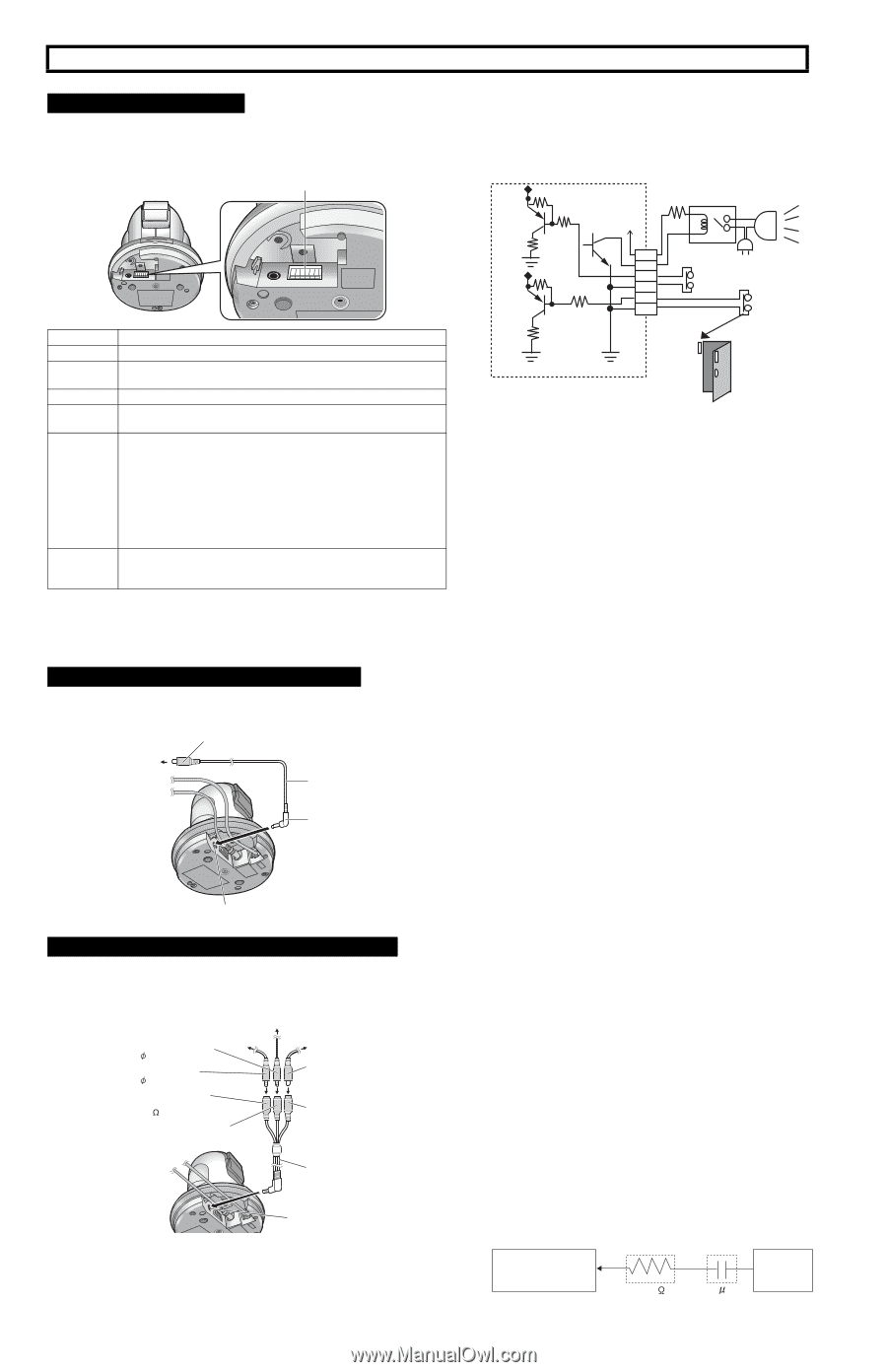
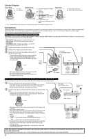
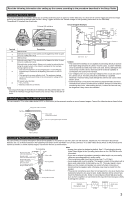
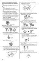
Read the following information after setting up the camera according to the procedure described in the Setup Guide. Connecting External Sensors The camera's external I/O interface allows you to connect 2 devices (such as sensors, motion detectors, etc.) that can be used to trigger the camera's image buffering and transferring features (see Section 2 Using Triggers to Buffer and Transfer Images in the Operating Instructions on the CD-ROM). The external I/O interface has 6 terminals. External I/O interface Circuit Diagram Example Camera Relay Light 12 V* 4 3 Door Sensor 2 (Alarm 2) 2 G Door Sensor 1 (Alarm 1) 1 G Terminal G 1 G 2 3 4 Description GND terminal. External sensor input 1. The camera can be triggered by either an open circuit or a GND short-circuit. GND terminal. External sensor input 2. The camera can be triggered by either an open circuit or a GND short-circuit. External device control output. Allows you to control an external device using the output buttons in the camera's operation bar (for example, turning a light on or off). • This terminal's behavior can be changed (see 7.4 Controlling the External Output Terminal in the Operating Instructions on the CDROM). • This terminal is an open collector circuit. The maximum drawing current is the same as terminal 4. Do not exceed the voltage of the terminal 4. DC power output terminal. • 10.5-13 V DC • Maximum load drive is 100 mA. Note • Do not push strongly on the external I/O interface with the pointed object. The external I/O interface may get stuck into the unit, and you may not be able to use it. *DC 10.5 V-13 V Caution • The external I/O interface is not capable of connecting directly to devices that require large amounts of current. In some cases, a custom interface circuit (customer-provided) may have to be used. Serious damage to the camera may result if a device that exceeds its electrical capability is connected to the external I/O interface. • Low voltage/current circuits and high voltage/current circuits are used in the camera circuit. All wiring should be performed by a qualified electrician. Incorrect wiring could damage the camera and cause a fatal electric shock. • External devices connected to the camera's output terminals cannot be controlled in the event of a network error or failure. Keep this in mind when connecting door locks, heat-emitting devices, or other devices that may be dangerous if they cannot be controlled. Connecting a Video Device (BB-HCM580A Only) You can connect a TV or other video device (NTSC or PAL format) to the camera to monitor or record camera images. Connect the video device as shown below. To TV Composite video connector Video cable (customer-provided) 3.5 mm L-type (right angle) connector Video terminal Connecting Audio/video Devices (BB-HCM581A Only) You can connect an external microphone and external speaker to the camera to use the Listen and Talk features, respectively. For information about these features, see 1.2.10 Audio Features in the Operating Instructions on the CD-ROM. You can also connect a TV or other video device (NTSC or PAL format) to the camera to monitor or record camera images. Connect the devices as shown below. To microphone To speaker Microphone cable ( 3.5 mm mini plug) Speaker cable ( 3.5 mm stereo mini plug) For speaker (red) (Output impedance 560 line level) For microphone (white) (Plug-in power +3.3 V) To TV Video cable For TV (yellow) Audio/video cord Audio/video terminal Note • Analog video output is disabled by default. See 7.5 Controlling the Analog Video Output Signal in the Operating Instructions on the CD-ROM for more information. • If you use an external microphone, excessive cable length or a poor quality cable can cause degradation in audio quality. • The microphone cable should be no longer than 7 m (23 feet). • Use a speaker with a built-in amplifier. The speaker connects to the camera with a stereo audio cable similar to that used by your PC. The output signal is mono. • Make sure the camera and speaker are turned off when connecting or disconnecting the speaker cable, otherwise noise may be heard from the speaker. • The external microphone input does not correspond to a line level. Audio may be distorted when the line level is input. Audio distortion will be solved if you insert the following circuits. Under no circumstance should high-level audio, such as from a speaker, be connected to this input terminal. Doing so is likely to damage the camera. Camera Microphone Input Resistor 33 K Capacitor 1 F Audio Line Out 3
-
 1
1 -
 2
2 -
 3
3 -
 4
4
 |
 |