Panasonic CF-19FHGAXAM Service Manual - Page 48
Setting the I/O PCB Ass'y, 2.11., Setting the Main PCB, Wireless Module, SD PCB, DU PCB,
 |
View all Panasonic CF-19FHGAXAM manuals
Add to My Manuals
Save this manual to your list of manuals |
Page 48 highlights
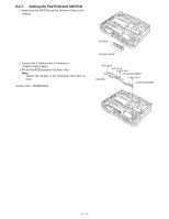
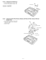
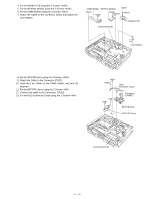
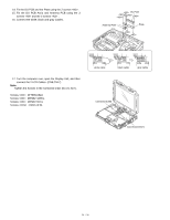
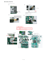
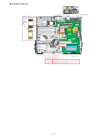
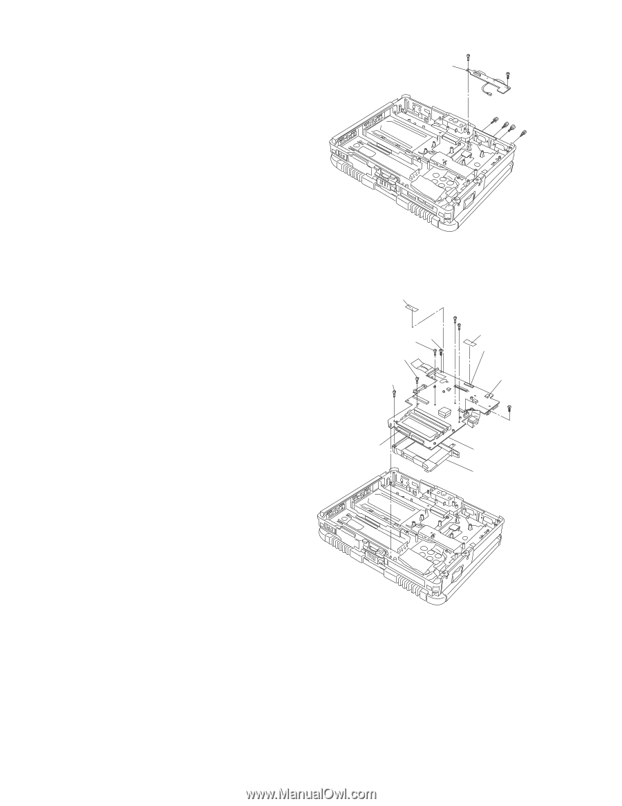
9.2.10. Setting the I/O PCB Ass'y 1. Fix the I/O PCB using the 2 Screws. 2. Fix the I/O PCB using the 4 Screws. Screws : DFHE5058ZB Screws : DRSB2+5FKL I/O PCB Ass'y 9.2.11. Setting the Main PCB, Wireless Module, SD PCB, DU PCB, Antenna PCB and Modem PCB 1. Fix the Main PCB using the 7 Screws . 2. Connect the 3 Cables to the 3 Connectors. (CN9,CN14,CN23) 3. Attach the Tape. Tape :No5 :No4 :No6 :No2 :No1 Tape Connector(CN9) Connector(CN14) :No7 Connector(CN23) Main PCB Combo Socket
-
 1
1 -
2
-
3
-
4
-
5
-
6
-
7
-
8
-
9
-
10
-
11
-
12
-
13
-
14
-
15
-
16
-
17
-
18
-
19
-
20
-
21
-
22
-
23
-
24
-
25
-
26
-
27
-
28
-
29
-
30
-
31
-
32
-
33
-
34
-
35
-
36
-
37
-
38
-
39
-
40
-
41
-
42
-
 43
43 -
 44
44 -
 45
45 -
 46
46 -
 47
47 -
 48
48 -
 49
49 -
 50
50 -
 51
51 -
 52
52 -
 53
53 -
54
-
55
-
56
-
57
-
58
-
59
-
60
-
61
-
62
-
63
-
64
-
65
-
66
-
67
-
68
-
69
-
70
-
71
-
72
-
73
-
74
-
75
-
76
-
77
-
78
-
79
-
80
-
81
-
82
-
83
-
84
-
85
-
86
-
87
-
88
-
89
-
90
 |
 |
9.2.10.
Setting the I/O PCB Ass'y
1.FixtheI/OPCBusingthe2Screws.<N9>
2.FixtheI/OPCBusingthe4Screws.<N2>
Screws<N2>:DFHE5058ZB
Screws<N9>:DRSB2+5FKL
9.2.11.
Setting the Main PCB, Wireless Module, SD PCB, DU PCB, Antenna PCB and
Modem PCB
1.FixtheMainPCBusingthe7Screws<N9>.
2.Connectthe3Cablestothe3Connectors.
(CN9,CN14,CN23)
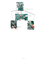
3.AttachtheTape.
<N9>
<N2>
<N2>
<N2>
<N2>
<N9>
I/OPCBAss'y
<N19>
:No1
<N19>
Tape
<N19>
:No4
<N19>
:No5
<N19>
:No6
<N19>
:No2
<N19>
:No7
MainPCB
ComboSocket
Connector(CN9)
Connector(CN14)
Connector(CN23)
Tape
48 / 90