Panasonic EY6932 EY6932 User Guide - Page 7
Operation - motor
 |
View all Panasonic EY6932 manuals
Add to My Manuals
Save this manual to your list of manuals |
Page 7 highlights
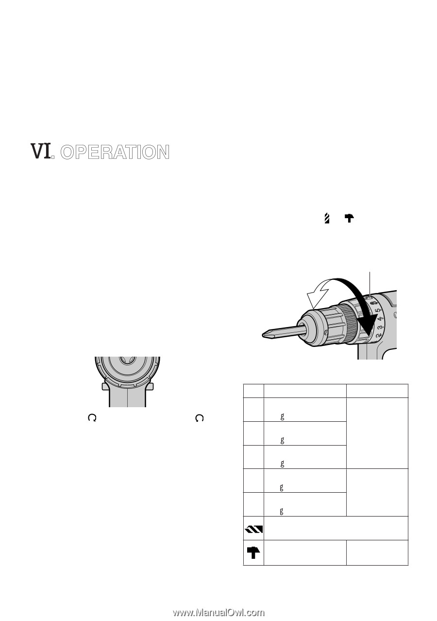
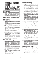
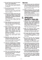
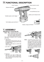
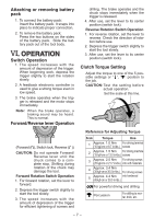
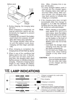
Attaching or removing battery pack 1. To connect the battery pack: Insert the battery pack. It snaps into place to indicate proper connection. 2. To remove the battery pack: Press the two buttons on the sides of the battery pack. Slide the battery pack out of the tool body. . OPERATION Switch Operation 1. The speed increases with the amount of depression of the trigger. When beginning work, depress the trigger slightly to start the rotation slowly. 2. A feedback electronic controller is used to give a strong torque even in low speed. 3. The brake operates when the trigger is released and the motor stops immediately. Note: When the brake operates, a braking sound may be heard. This is normal. Forward/Reverse lever Operation drilling. The brake operates and the chuck stops immediately when the trigger is released. 4. After use, set the lever to its center position (switch lock). Reverse Rotation Switch Operation 1. For reverse rotation, set the lever to reverse. Check the direction of rotation before use. 2. Depress the trigger switch slightly to start the tool slowly. 3. After use, set the lever to its center position (switch lock). Clutch Torque Setting Adjust the torque to one of the 5 possible settings or " ", " " position to the job. CAUTION: Test the setting before actual operation. Set the scale at this line. (Forward ( ), Switch lock, Reverse ( )) CAUTION: Do not operate Forward/ Reverse lever until the chuck comes to a complete stop. Shifting during rotation of the chuck may damage the tool. Forward Rotation Switch Operation 1. For forward rotation, set the lever to forward. 2. Depress the trigger switch slightly to start the tool slowly. 3. The speed increases with the amount of depression of the trigger for efficient tightening of screws and Reference for Adjusting Torque Scale Torque Use 1 Approx. 1.0 Nm (10 k f-cm or 8.7 in-lbs.) For driving terminal screws 2 Approx. 1.5 Nm For driving machine (15 k f-cm or 13.0 in-lbs.) screws 3 Approx. 2.5 Nm For driving screws (25 k f-cm or 21.7 in-lbs.) into soft materials 4 Approx. 3.4 Nm (35 k f-cm or 30.5 in-lbs.) For driving screws 5 Approx. 4.4 Nm into hardwood (45 k f-cm or 39.0 in-lbs.) For powerful driving and drilling Percussion For drilling to mortar, brick, etc. - 7 -
-
 1
1 -
 2
2 -
 3
3 -
 4
4 -
 5
5 -
 6
6 -
 7
7 -
 8
8 -
 9
9 -
 10
10 -
 11
11 -
 12
12
 |
 |