Panasonic FV-08WQ1 Installation Instructions - Page 5
Installation, In new construction
 |
View all Panasonic FV-08WQ1 manuals
Add to My Manuals
Save this manual to your list of manuals |
Page 5 highlights
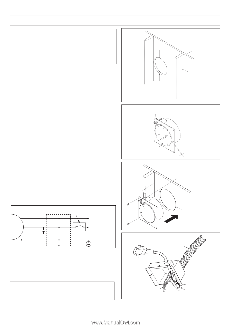
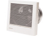
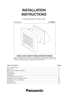
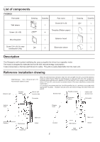
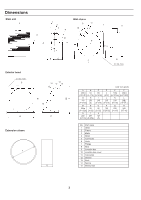
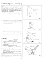
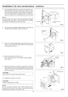
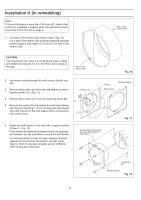
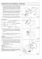
Installation I (In new construction) NOTE: If the wall thickness is more than 152.4 mm (6"), refer to the reference installation drawing when the wall thickness is more than 152.4 mm (6") on page 2. However, this ventilating fan can be installed on an interior wall with a thickness of 12.7 - 16 mm (1/2 - 5/8"). For installation on other walls, refer to the method on page 7, Installation II. 1. Cut a 215 mm (8 1/2") diameter hole in the wall. (Fig. 1) (Cut the hole next to a wall stud as shown in the figure.). 2. Adjust position of the flange on the wall sleeve (Fig. 2). Loosen the three screws (arrow pointed) and slide the wall sleeve horizontally to adjust its position to compensate for the thickness of the interior wall (A). When this has been done, tighten all three screws. Exterior wall 8 1/2" diameter Flange Stud Fig. 1 3. After providing a 3 mm notch in the wall stud, secure the flange to the wall stud with supplied screws (Screw I). (Fig. 3) 4. Remove the junction box cover by removing screw (B). 5. Remove one of the knockout holes in the junction box. Wiring Diagram White Motor Black Red Green Junction box Switch (Available on the market) Power supply AC 120 V 60 Hz Green Earth ground 6. Refer to the wiring diagram above. Using the wire nuts, connect the house power wires to ventilating fan wires. (Fig. 4): black to black; white to white; green to greens. Reattach the junction box cover. CAUTION: Reattach the junction box cover carefully so that the lead wires are not pinched by the cover. 5 Wall sleeve A Fig. 2 13/m8"m Knockout hole B Hole in the wall Fig. 3 Connector Flexible conduit Green Black White Fig. 4
-
 1
1 -
 2
2 -
 3
3 -
 4
4 -
 5
5 -
 6
6 -
 7
7 -
 8
8 -
 9
9 -
 10
10 -
 11
11 -
12
-
13
-
14
-
15
-
16
-
17
-
18
-
19
-
20
 |
 |