Panasonic FV08VS1 FV08VKL1 User Guide - Page 5
Important
 |
View all Panasonic FV08VS1 manuals
Add to My Manuals
Save this manual to your list of manuals |
Page 5 highlights
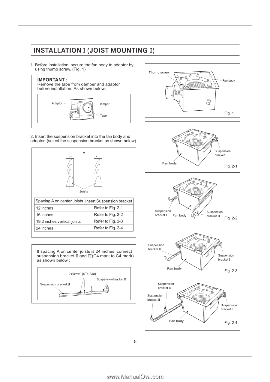
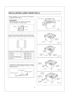
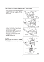
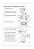
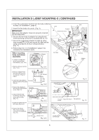
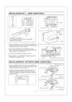
INSTALLATION I (JOIST MOUNTING-I) 1. Before installation, secure the fan body to adaptor by using thumb screw. (Fig. 1) IMPORTANT : Remove the tape from damper and adaptor before installation. As shown below: Thumb screw Adaptor _ - Damper Tape Fan body 00- Fig. 1 2. Insert the suspension bracket into the fan body and adaptor. (select the suspension bracket as shown below) A i1 it Joists Spacing A on center Joists Insert Suspension bracket 12 inches Refer to Fig. 2-1 16 inches Refer to Fig. 2-2 19.2 inches vertical joists Refer to Fig. 2-3 24 inches Refer to Fig. 2-4 0 " Q. Fan body Suspension bracket I Fig. 2-1 e ..:. Suspension e . bracket I Fan body ode Suspension bracket M Fig. 2-2 If spacing A on center joists is 24 inches, connect suspension bracket II and III(C4 mark to C4 mark) as shown below : 2 Screw I (ST4.2X8) Suspension bracketIII Suspension bracket II Suspension bracket M 0 " ,„ o Fan body Suspension bracket III Suspension bracket II "Cl t~Qll.ll 0 .. ,V Fan body j Suspension bracket I Fig. 2-3 a ° Suspension bracket I Fig. 2-4 5
-
 1
1 -
 2
2 -
 3
3 -
 4
4 -
 5
5 -
 6
6 -
 7
7 -
 8
8 -
 9
9 -
 10
10 -
 11
11 -
12
 |
 |