Panasonic FV15VQL4 Installation Instructions - Page 11
joists.Fig.17
 |
View all Panasonic FV15VQL4 manuals
Add to My Manuals
Save this manual to your list of manuals |
Page 11 highlights
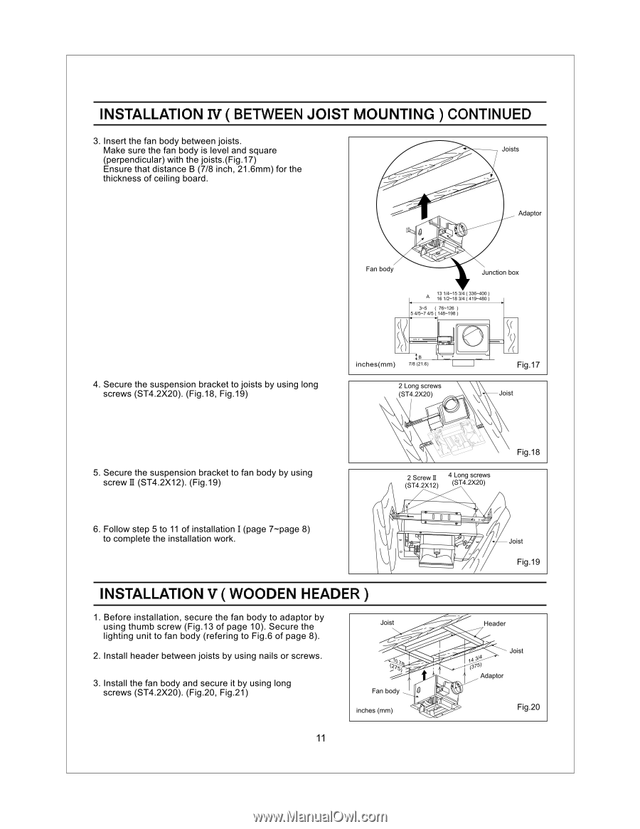
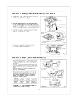
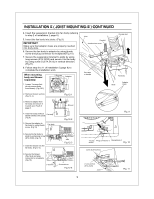
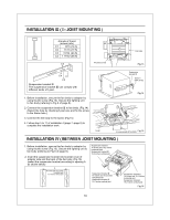
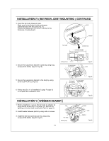
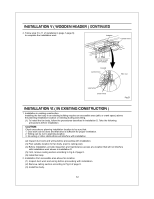
INSTALLATION IV ( BETWEEN JOIST MOUNTING ) CONTINUED 3. Insert the fan body between joists. Make sure the fan body is level and square Joists (perpendicular) with the joists.(Fig.17) Ensure that distance B (7/8 inch, 21.6mm) for the thickness of ceiling board. Adaptor 0 Fan body Junction box 13 1/4-15 3/4 (336-400) A 16 1/2-183/4 (419-480) 3-5 ( 76-126 ) 5 4/5-7 4/5 ( 48-198 4. Secure the suspension bracket to joists by using long screws (ST4.2X20). (Fig.18, Fig.19) inches(mm) :a 7/8(21.6) 2 Long screws (ST4.2X20) Fig.17 Joist 5. Secure the suspension bracket to fan body by using screw II (ST4.2X12). (Fig.19) 6. Follow step 5 to 11 of installation I (page 7-page 8) to complete the installation work. 2 Screw II (ST4.2X12) 4 Long screws (ST4.2X20) Fig.18 0 0 0 .47 Joist Fig.19 INSTALLATION V ( WOODEN HEADER ) 1. Before installation, secure the fan body to adaptor by using thumb screw (Fig.13 of page 10). Secure the Joist lighting unit to fan body (refering to Fig.6 of page 8). 2. Install header between joists by using nails or screws. 3. Install the fan body and secure it by using long screws (ST4.2X20). (Fig.20, Fig.21) Fan body inches (mm) Header Joist 14 514 070 Adaptor Fig.20 11
-
 1
1 -
2
-
3
-
4
-
5
-
 6
6 -
 7
7 -
 8
8 -
 9
9 -
 10
10 -
 11
11 -
 12
12 -
 13
13 -
 14
14 -
 15
15
 |
 |