Panasonic SA-XR55S SAXR55 User Guide - Page 13
Setting - Test, Test
 |
View all Panasonic SA-XR55S manuals
Add to My Manuals
Save this manual to your list of manuals |
Page 13 highlights
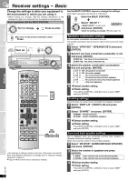
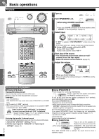
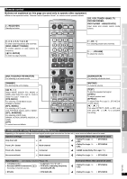
Changing the digital input terminals Change these settings to suit the connections you have made to the optical (OPT) and coaxial (COAX) digital input terminals. (ápages 4, 5, 9 and 10) You can only allocate one piece of equipment per terminal. 2 Select "D-INPUT " (DIGITAL INPUT) and press [ENTER]. 3 Select the input position and press [ENTER]. TV/STB, DVR, DVD, CD 4 Change the setting and press [ENTER]. Repeat steps 3 and 4 to set other input positions. OPT 1, OPT 2, COAX 1, COAX 2 5 Select another setting Press [MULTI CONTROL, CANCEL] several times to return to step 2 in the operations across and select another setting. Finish setting Press [MULTI CONTROL, CANCEL] several times to select "EXIT " and press [ENTER]. Input signal settings This unit automatically detects whether input is digital or analog, but you can fix the input mode. Select "AUTO " when it is not necessary to fix the signal. 2 Select "IN MODE " (INPUT MODE) and press [ENTER]. 3 Select the input position and press [ENTER]. TV/STB, DVR, DVD, CD 4 Change the setting and press [ENTER]. AUTO: Automatically detects the input signal and plays. (In "AUTO", the unit distinguishes the digital signals then the analog signals.) ANALOG: Fixes the input signal to analog and plays. DIGITAL: Fixes the input signal to digital and plays. PCM FIX: Fixes the input signal to PCM and plays. Repeat steps 3 and 4 to set other input positions. 5 Select another setting Press [MULTI CONTROL, CANCEL] several times to return to step 2 in the operations across and select another setting. Finish setting Press [MULTI CONTROL, CANCEL] several times to select "EXIT " and press [ENTER]. Note regarding PCM FIX mode In rare cases, the unit may have trouble recognizing the digital signals on discs. With the PCM signals on CDs, this may cause the beginning of a track to be cut off. Engage the PCM FIX mode if this occurs. When PCM FIX mode is on, the unit cannot process other signals. This may cause noise to be output. Select another mode in this case. • This setting is not necessary when playback is normal. • When an input position is set to PCM FIX, and the input signals are not from a PCM source, "PCM FIX " flashes on the display. Before use Connections Settings Settings - Test Check that sound is output from the connected speakers. • Adjust so output level from each speaker is balanced with the output level from the front speakers. L: Front left C: Center R: Front right RS: Surround right LS: Surround left SBL: Surround back left SBR: Surround back right SB: Surround back (If you connect one surround back speaker) SW: Subwoofer 1 Turn SPEAKERS A on. SPEAKERS A B -When using a BI-WIRE connection- • If you select SPEAKERS B only, the test signal will not be output. 2 Check the test signal output. A test signal is output from one speaker at a time for two seconds in the following order. • Speakers set as "_" (not connected) in "Speakers combination settings" (ápage 12) are skipped. If there is no output from a connected speaker, Stop the test signal (step 6) and check the connections (ápages 6 to 8) and settings (ápage 12, left) again. 3 Adjust the main volume. VOL- 50dB (MIN) (MAX) 4 Select the speaker channel. 5 Adjust the level. • Adjust center, surround and surround back output to the same apparent level as the front speakers. C +4dB (MIN) (MAX) Factory settings: 0 dB SW 10 Factory setting: 10 • Approximately two seconds after adjusting the level, a test signal is again output from each speaker in order. Repeat steps 4 and 5 to adjust the level of each speaker. 6 Stop the test signal. Operations Basic Operations Reference RQT7994 13
-
 1
1 -
2
-
3
-
4
-
5
-
6
-
7
-
 8
8 -
 9
9 -
 10
10 -
 11
11 -
 12
12 -
 13
13 -
 14
14 -
 15
15 -
 16
16 -
 17
17 -
 18
18 -
19
-
20
-
21
-
22
-
23
-
24
-
25
-
26
-
27
-
28
 |
 |