Panasonic fv05vf2 FV05VK1 User Guide - Page 8
Installation, Joist, Mounting, Continued
 |
View all Panasonic fv05vf2 manuals
Add to My Manuals
Save this manual to your list of manuals |
Page 8 highlights
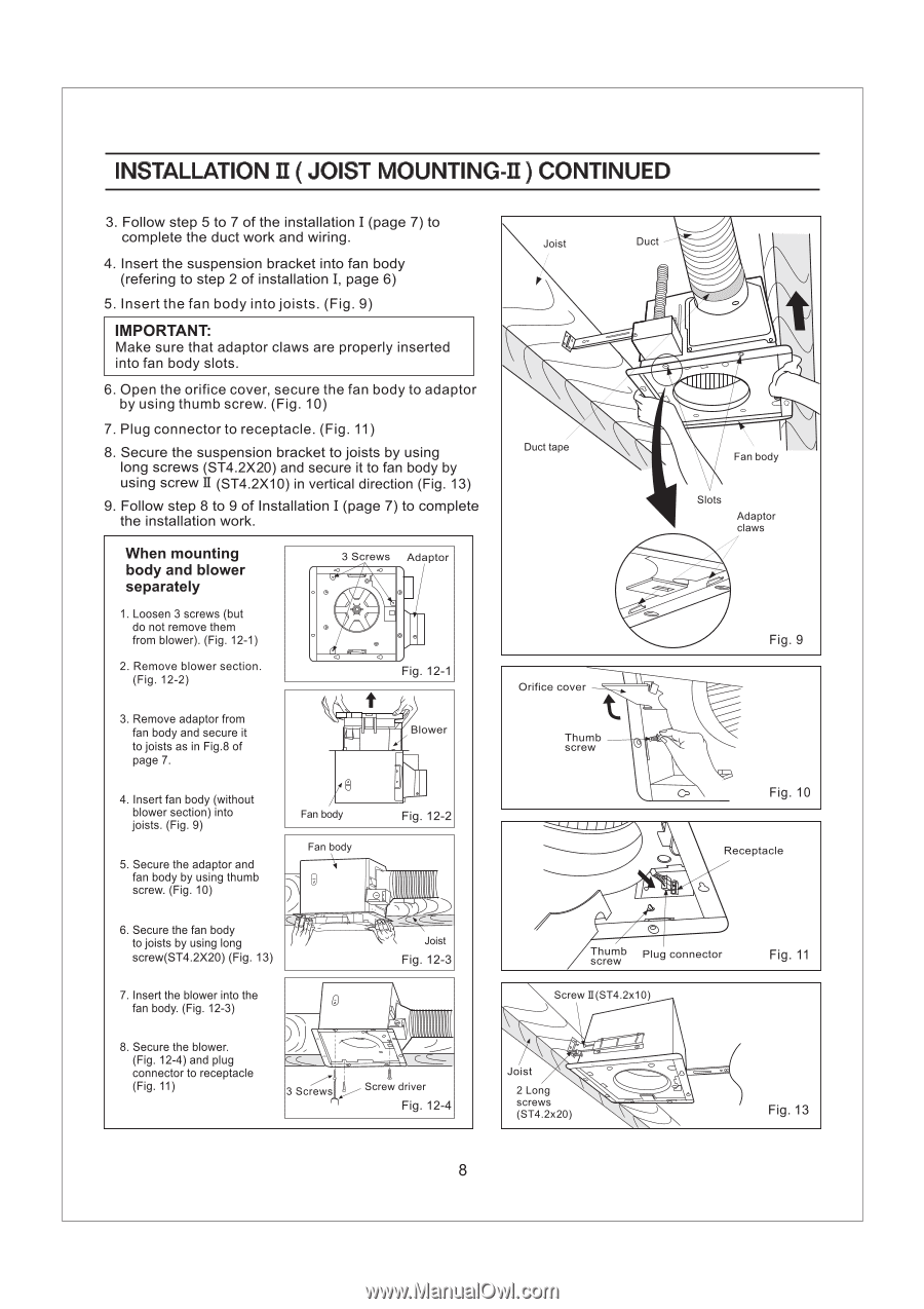
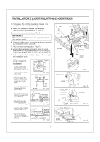
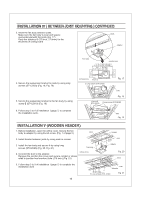
INSTALLATION II ( JOIST MOUNTING-II ) CONTINUED 3. Follow step 5 to 7 of the installation I (page 7) to complete the duct work and wiring. 4. Insert the suspension bracket into fan body (refering to step 2 of installation I, page 6) 5. Insert the fan body into joists. (Fig. 9) IMPORTANT: Make sure that adaptor claws are properly inserted into fan body slots. 6. Open the orifice cover, secure the fan body to adaptor by using thumb screw. (Fig. 10) 7. Plug connector to receptacle. (Fig. 11) 8. Secure the suspension bracket to joists by using long screws (ST4.2X20) and secure it to fan body by using screw II (ST4.2X10) in vertical direction (Fig. 13) 9. Follow step 8 to 9 of Installation I (page 7) to complete the installation work. When mounting body and blower separately 1. Loosen 3 screws (but do not remove them from blower). (Fig. 12-1) 2. Remove blower section. (Fig. 12-2) 3 Screws Adaptor Fig. 12-1 3. Remove adaptor from fan body and secure it to joists as in Fig.8 of page 7. 4. Insert fan body (without blower section) into joists. (Fig. 9) 5. Secure the adaptor and fan body by using thumb screw. (Fig. 10) Blower 8 Fan body Fan body Fig. 12-2 0 • 6. Secure the fan body to joists by using long screw(ST4.2X20) (Fig. 13) Joist Fig. 12-3 7. Insert the blower into the fan body. (Fig. 12-3) Joist Duct 0 Duct tape Fan body Slots Adaptor claws Orifice cover Thumb screw Fig. 9 Fig. 10 Receptacle (2) Thumb screw Plug connector Screw II(ST4.2x10) Fig. 11 8. Secure the blower. (Fig. 12-4) and plug connector to receptacle (Fig. 11) 3 Screws Screw driver Fig. 12-4 Joist 2 Long screws (ST4.2x20) Fig. 13 8
-
 1
1 -
2
-
 3
3 -
 4
4 -
 5
5 -
 6
6 -
 7
7 -
 8
8 -
 9
9 -
 10
10 -
 11
11 -
 12
12
 |
 |