Philips 42PFL7704D User manual - Page 32
Connect your devices
 |
UPC - 609585162754
View all Philips 42PFL7704D manuals
Add to My Manuals
Save this manual to your list of manuals |
Page 32 highlights
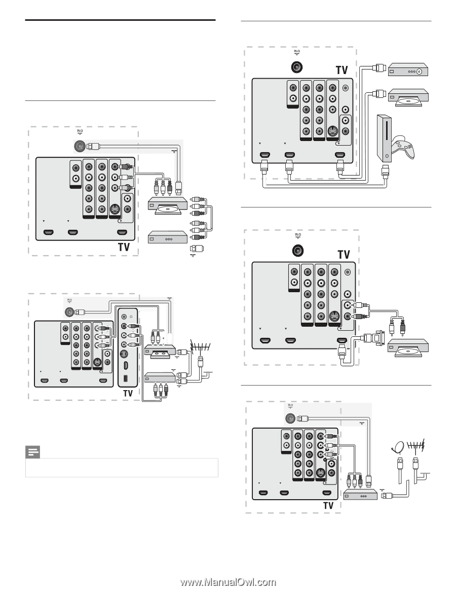
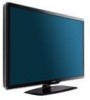
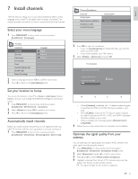
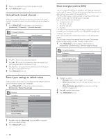
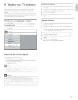
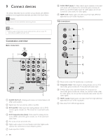
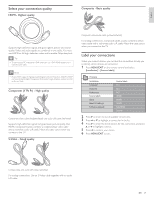
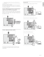
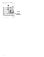
Connect your devices This section describes how to connect a selection of devices with different connectors. Different types of connectors can be used to connect a device to your TV.The following sections describe examples only, other configurations are possible. When you connect composite or component cables, match the cable colors to the connectors on the TV. Connect a DVD player/recorder via composite connectors TV ANTENNA Or/Ou/O RF OUT R R R R SERV. U L L L L L + R + VIDEO Pr Pr L/R OUT SPDIF OUT OUT Pb Pb VIDEO L IN Y Y S-VIDEO R HDMI 1 AV 1 HDMI 2 AV 2 AV 3 DVI AUDIO IN HDMI 3 RECO RD ER Set-top box OUT RF IN Do not place your recorder too close to the screen because some recorders can be susceptible to signals. TV ANTENNA HDMI 1 R R R R SERV. U L L L L Pr Pr L/R OUT SPDIF OUT Pb Pb Y Y VIDEO L S-VIDEO R AV 1 HDMI 2 AV 2 AV 3 DVI AUDIO IN HDMI 3 Or/Ou/O RF OUT L + R + VIDEO R AUDIO L VIDEO S-VIDEO HDMI 4 USB OUT RECORDER OUT RF IN RF OUT RF IN CABLE L + R + VIDEO If your recorder has an S-VHS video jack: For improved picture quality, connect an S-Video cable with the S-Video input. Connect the audio cables to the audio L and R input jacks of AV3/side AV. Note • When you use an S-Video connector, do not connect any device to the AV3/side AV video jack. If you use mono equipment, the left loudspeaker reproduces sound but the right speaker does not. Use a mono to stereo adapter (not supplied) for sound reproduction via all internal loudspeakers. 30 EN Connect a set-top box, DVD player/recorder and game console via HDMI TV ANTENNA HDMI 1 R R R R SERV. U L L L L L/R OUT Pr Pr SPDIF OUT Pb Pb Y Y VIDEO L S-VIDEO R HDMI 2 AV 1 AV 2 AV 3 DVI AUDIO IN HDMI 3 Connect a DVD player/recorder via HDMI-DVI and DIGITAL AUDIO OUT connectors TV ANTENNA HDMI 1 R R R R SERV. U L L L L L/R OUT Pr Pr Pb Pb SPDIF OUT VIDEO L AUDIO IN Y Y S-VIDEO R HDMI 2 AV 1 AV 2 AV 3 DVI AUDIO IN HDMI 3 DVI H D MI AUDIO OUT Connect a set-top box via a composite connector HDMI 1 TV ANTENNA R R R R Or/Ou/O RF OUT SERV. U L L L L Pr Pr L/R OUT L + R + VIDEO SPDIF OUT Pb Pb Y Y VIDEO L S-VIDEO R AV 1 AV 2 AV 3 DVI AUDIO IN HDMI 2 HDMI 3 OUT Set-top box RF IN CABLE If your device has an S-VHS video jack, improve the picture quality as follows: • Connect an S-Video cable to the S-Video input of AV3/side AV
-
 1
1 -
2
-
3
-
4
-
5
-
6
-
7
-
8
-
9
-
10
-
11
-
12
-
13
-
14
-
15
-
16
-
17
-
18
-
19
-
20
-
21
-
22
-
23
-
24
-
25
-
26
-
 27
27 -
 28
28 -
 29
29 -
 30
30 -
 31
31 -
 32
32 -
 33
33 -
 34
34 -
 35
35 -
 36
36 -
 37
37 -
38
-
39
-
40
 |
 |