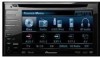
Pioneer AVH P3100DVD Installation Manual - Page 3
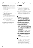
Connecting the units - wiring
 |
UPC - 012562944050
View all Pioneer AVH P3100DVD manuals
Add to My Manuals
Save this manual to your list of manuals |
Page 3 highlights
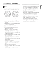
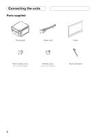
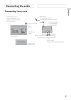
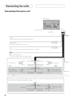
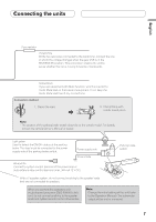
English N STAR N STAR Connecting the units Note • This unit cannot be installed in a vehicle without ACC (accessory) position on the ignition switch. F ACC O F O OF OF T T ACC position No ACC position • Use this unit in other than the following conditions could result in fire or malfunction. - Vehicles with a 12-volt battery and negative grounding. - Speakers with 50 W (output value) and 4 ohm to 8 ohm (impedance value). • To prevent short-circuit, overheating or malfunction, be sure to follow the directions below. - Disconnect the negative terminal of the battery before installation. - Secure the wiring with cable clamps or adhesive tape. To protect the wiring, wrap adhesive tape around them where they lie against metal parts. - Place all cables away from moving parts, such as gear shift and seat rails. - Place all cables away from hot places, such as near the heater outlet. - Do not pass the yellow cable through a hole into the engine compartment to connect to a battery. - Cover any disconnected cable connectors with insulating tape. - Do not shorten any cables. - Never cut the insulation of the power cable of this unit in order to share the power to other equipment. Current capacity of the cable is limited. - Use a fuse of the rating prescribed. - Never wire the speaker negative cable directly to ground. - Never band together multiple speaker's negative cables. • Control signal is output through blue/white cable when this unit is powered on. Connect it to an external power amp's system remote control or the vehicle's auto-antenna relay control terminal (max. 300 mA, 12 V DC). If the vehicle is equipped with a glass antenna, connect it to the antenna booster power supply terminal. • Never connect blue/white cable to external power amp's power terminal. Also, never connect it to the power terminal of the auto antenna. Otherwise, battery drain or malfunction may result. • IP-BUS connectors are color-coded. Be sure to connect connectors of the same color. • Black cable is ground. This cable and other product's ground cable (especially, high-current products such as power amp) must be wired separately. Otherwise, fire or malfunction may result if they are accidentally detached. 3
-
 1
1 -
 2
2 -
 3
3 -
 4
4 -
 5
5 -
 6
6 -
 7
7 -
 8
8 -
 9
9 -
10
-
11
-
12
-
13
-
14
-
15
-
16
-
17
-
18
-
19
-
20
-
21
-
22
-
23
-
24
-
25
-
26
-
27
-
28
-
29
-
30
-
31
-
32
-
33
-
34
-
35
-
36
-
37
-
38
 |
 |