Pioneer AVH-P6600DVD Other Manual - Page 1
Pioneer AVH-P6600DVD Manual
 |
UPC - 012562682853
View all Pioneer AVH-P6600DVD manuals
Add to My Manuals
Save this manual to your list of manuals |
Page 1 highlights
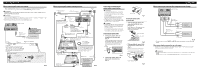
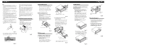
INSTALLATION MANUAL OF OF AVH-P6600DVD This product conforms to CEMA cord colors. Le code de couleur des câbles utilisé pour ce produit est conforme à CEMA. Printed in Japan Imprimé au Japon UC N STAR N STAR MANUEL D'INSTALLATION Connecting the Units CAUTION: • PIONEER does not recommend that you install or service your display yourself. Installing or servicing the product may expose you to risk of electric shock or other hazards. Refer all installation and servicing of your display to authorized Pioneer service personnel. • Secure all wiring with cable clamps or electrical tape. Do not allow any bare wiring to remain exposed. • Do not drill a hole into the engine compartment to connect the yellow lead of the unit to the vehicle battery. Engine vibration may eventually cause the insulation to fail at the point where the wire passes from the passenger compartment into the engine compartment. Take extra care in securing the wire at this point. • It is extremely dangerous to allow the display lead to become wound around the steering column or gearshift. Be sure to install the display in such a way that it will not obstruct driving. • Make sure that wires will not interfere with moving parts of the vehicle, such as the gearshift, parking brake or seat sliding mechanism. • Do not shorten any leads. If you do, the protection circuit may fail to work properly. WARNING LIGHT GREEN LEAD AT POWER CONNECTOR IS DESIGNED TO DETECT PARKED STATUS AND MUST BE CONNECTED TO THE POWER SUPPLY SIDE OF THE PARKING BRAKE SWITCH. IMPROPER CONNECTION OR USE OF THIS LEAD MAY VIOLATE APPLICABLE LAW AND MAY RESULT IN SERIOUS INJURY OR DAMAGE. WARNING • To avoid the risk of accident and the potential vio- lation of applicable laws, the front DVD or TV (sold separately) feature should never be used while the vehicle is being driven. Also, Rear Displays should not be in a location where it is a visible distraction to the driver. • In some countries or states the viewing of images on a display inside a vehicle even by persons other than the driver may be illegal. Where such regulations apply, they must be obeyed and this unit's DVD features should not be used. ENGLISH> Note: • This unit is for vehicles with a 12-volt battery and negative grounding. Before installing it in a recreational vehicle, truck, or bus, check the battery voltage. • To avoid shorts in the electrical system, be sure to disconnect the ≠ battery cable before beginning installation. • Refer to the owner's manual for details on connecting the power amp and other units, then make connections correctly. • Secure the wiring with cable clamps or adhesive tape. To protect the wiring, wrap adhesive tape around them where they lie against metal parts. • Route and secure all wiring so it cannot touch any moving parts, such as the gear shift, handbrake and seat rails. Do not route wiring in places that get hot, such as near the heater outlet. If the insulation of the wiring melts or gets torn, there is a danger of the wiring short-circuiting to the vehicle body. • Don't pass the yellow lead through a hole into the engine compartment to connect to the battery. This will damage the lead insulation and cause a very dangerous short. • Do not shorten any leads. If you do, the protection circuit may fail to work when it should. • Never feed power to other equipment by cutting the insulation of the power supply lead of the unit and tapping into the lead. The current capacity of the lead will be exceeded, causing overheating. • When replacing fuse, be sure to use only fuse of the rating prescribed on the fuse holder. • Since a unique BPTL circuit is employed, never wire so the speaker leads are directly grounded or the left and right ≠ speaker leads are common. • If the RCA pin jack on the unit will not be used, do not remove the caps attached to the end of the connector. • Speakers connected to this unit must be highpower types with minimum rating of 50 W and impedance of 4 to 8 ohms. Connecting speakers with output and/or impedance values other than those noted here may result in the speakers catching fire, emitting smoke or becoming damaged. • When this product's source is switched ON, a control signal is output through the blue/white lead. Connect to an external power amp's system remote control or the car's Auto-antenna relay control terminal (max. 300 mA 12 V DC). If the car features a glass antenna, connect to the antenna booster power supply terminal. • When an external power amp is being used with this system, be sure not to connect the blue/white lead to the amp's power terminal. Likewise, do not connect the blue/white lead to the power terminal of the auto-antenna. Such connection could cause excessive current drain and malfunction. • To avoid short-circuiting, cover the disconnected lead with insulating tape. Especially, insulate the unused speaker leads without fail. There is a possibility of short-circuiting if the leads are not insulated. • To prevent incorrect connection, the input side of the IP-BUS connector is blue, and the output side is black. Connect the connectors of the same colors correctly. • This unit cannot be installed in a vehicle that does not have an ACC (accessory) position on the ignition switch. (Fig. 1) F ACC O F O T T ACC position No ACC position Fig. 1 • The black lead is ground. Please ground this lead separately from the ground of high-current products such as power amps. If you ground the products together and the ground becomes detached, there is a risk of damage to the products or fire. • Cords for this product and those for other products may be different colors even if they have the same function. When connecting this product to another product, refer to the supplied manuals of both products and connect cords that have the same function.
-
 1
1 -
 2
2 -
 3
3 -
 4
4 -
 5
5 -
 6
6 -
 7
7 -
8
 |
 |