Pioneer AVH-P6600DVD Other Manual - Page 3
When connecting with a rear view camera - installation
 |
UPC - 012562682853
View all Pioneer AVH-P6600DVD manuals
Add to My Manuals
Save this manual to your list of manuals |
Page 3 highlights
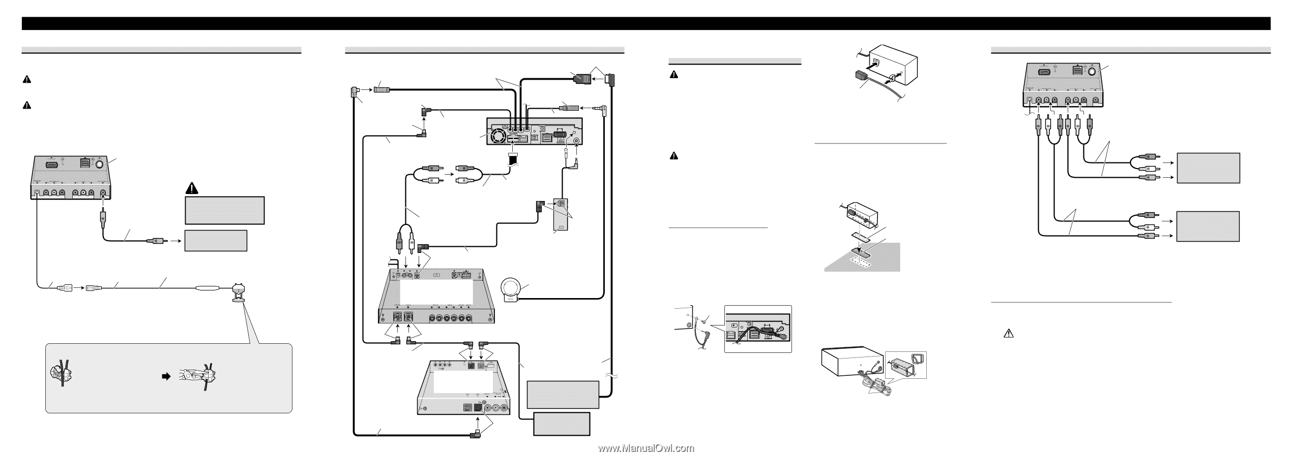
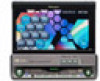
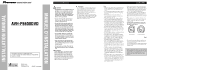
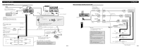
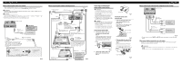
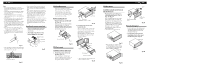
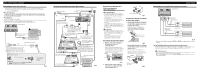
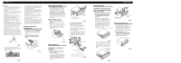
Connecting the Units When connecting with a rear view camera When using this product with a rear view camera, automatic switching to video from a rear view camera when the gear shift is moved to REVERSE (R) position is possible. WARNING USE INPUT ONLY FOR REVERSE OR MIRROR IMAGE REAR VIEW CAMERA. OTHER USE MAY RESULT IN INJURY OR DAMAGE. CAUTION • The screen image may appear reversed. • The rear view camera function is to use this product as an aid to keep an eye on trailers, or backing into a tight parking spot. Do not use this function for entertainment purposes. • The object in rear view may appear closer or more distant than in reality. Hide-away unit RCA cable (sold separately) CAUTION You must use a camera which outputs mirror reversed images. To video output rear view camera 10 cm (3-7/8 in.) 8m (26 ft. 3 in.) Extension lead (supplied) Violet/white Of the two lead wires connected to the back lamp, connect the one in which the voltage changes when the gear shift is in the REVERSE (R) position. This connection enables the unit to sense whether the car is moving forwards or backwards. Connection method Fuse resistor 1. Clamp the lead. 2. Clamp firmly with needle-nosed pliers. Note: • It is necessary to set to BACK UP CAMERA in SETUP when connecting the rear view camera. Fig. 4 When connecting with a multi-channel processor AV-BUS input (Blue) 40 cm (1 ft. 4 in.) 26 pin cable input Yellow IP-BUS input (Blue) Blue Blue 15 cm (5-7/8 in.) Guide speaker output (GUIDE SP OUTPUT) 15 cm IP-BUS cable (supplied with multi-channel processor) This product Black 23 cm (9 in.) Subwoofer output or non fading output (SUBWOOFER OUTPUT or NON-FADING OUTPUT) RCA cable (supplied with multi-channel processor) Black Optical cable connection box (supplied with multi-channel processor) Blue Optical cable (supplied with multi-channel processor) Multi-channel processor (DEQ-P8000) (sold separately) Blue Guide speaker (e.g. CD-TS37GP) (sold separatly) If you use this unit with navigation unit (e.g. AVIC-88DVD) and multi-channel processor (e.g. DEQ-P8000), be sure to connect a guide speaker to this unit's guide speaker output terminal. IP-BUS cable Black Blue (supplied with TV tuner) Hide-away TV tuner (e.g. GEX-P6400TV) (sold separately) IP-BUS cable 26 pin cable Navigation unit (e.g. AVIC-88DVD) (sold separately) AV-BUS cable (supplied with TV tuner) Black Multi-CD player (sold separately) Fig. 5 Connecting and installing the optical cable connection box WARNING • Avoid installing this unit in such a location where the operation of safety devices such as airbags is prevented by this unit. Otherwise, there is a danger of a fatal accident. • Avoid installing this unit in such a location where the operation of the brake may be prevented. Otherwise, it may result in a traffic accident. • Fix this unit securely with the velcro tape or lock tie. If this unit is loose, it disturbs driving stability, which may result in a traffic accident. CAUTION • Install this unit using only the parts supplied with this unit. If other parts are used, this unit may be damaged or could dismount itself, which leads to an accident or trouble. • Do not install this unit near the doors where rainwater is likely to be spilled on the unit. Incursion of water into the unit may cause smoke or fire. Connecting the optical cable 1. Connect the optical cable and ground lead to the main unit. (Fig. 6) Connect the optical cable so that it does not protrude from the unit, as shown in the illustration. Fasten the ground lead to the protrusion on the back of the unit. Screw Fig. 6 2. Connect the optical cable to the optical cable connection box. (Fig. 7) Optical cable Fig. 7 Installing the optical cable connection box • When installing the optical cable connection box with the velcro tape. (Fig. 8) Install the optical cable connection box using the velcro tape in the ample space of the console box. Velcro tape (hard) Velcro tape (soft) Fig. 8 • When installing the optical cable connection box with the lock tie. (Fig. 9) Wrap the optical cable and connection box with the protection tape and fasten with the power code using the lock tie. Wrap with the protection tape Fasten with the lock tie Fig. 9 When connecting the external video component and the display Hide-away unit RCA cables (sold separately) To audio outputs RCA cables (sold separately) To video output To audio inputs External video component (sold separately) To video input Display with RCA input jacks Fig. 10 • It is necessary to set to AV INPUT in SET UP when connecting the external video com- ponent. When using a display connected to rear video output This product's rear video output is for connection of a display to enable passengers in the rear seats to watch the DVD or Video CD. WARNING: • NEVER install the display in a location that enables the Driver to watch the DVD or Video CD while Driving. • NEVER connect rear audio output (REAR MONITOR OUT) to sold separately power amp.
-
 1
1 -
 2
2 -
 3
3 -
 4
4 -
 5
5 -
 6
6 -
 7
7 -
 8
8
 |
 |