Pioneer AVHP6000DVD Other Manual - Page 2
Connecting the Units, <ENGLISH> - vehicle applications
 |
UPC - 012562890685
View all Pioneer AVHP6000DVD manuals
Add to My Manuals
Save this manual to your list of manuals |
Page 2 highlights
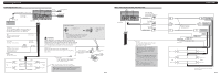
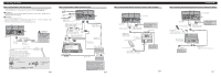
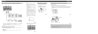
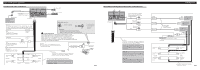
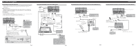
Connecting the Units Connecting the power cord IP-BUS input (Blue) 16 cm (6-1/4 in.) Violet/white Refer to Fig. 4. 20 cm (7-7/8 in.) AUX input jack 15 cm Antenna cable (5-7/8 in.) IP-BUS cable Multi-CD player (sold separately) This product Yellow/black If you use equipment with Mute function, wire this lead to the Audio Mute lead on that piece of equipment. If not, keep the Audio Mute lead free of any connections. Red To electric terminal controlled by ignition switch (12 V DC) ON/OFF. Fuse resistor Orange/white To lighting switch terminal. Fuse resistor Yellow To terminal always supplied with power regardless of ignition switch position. Fuse (10 A) Black (ground) To vehicle (metal) body. + Front speaker ≠ Left + Rear speaker ≠ White White/black Green Gray Gray/black Violet Green/black Violet/black Connection method 1. Clamp the lead. WARNING Note: • The position of the parking brake switch depends on the vehicle model. For details, consult the vehicle Owner's Manual or dealer. LIGHT GREEN LEAD AT POWER CONNECTOR IS DESIGNED TO DETECT PARKED STATUS AND MUST BE CONNECTED TO THE POWER SUPPLY SIDE OF THE PARKING BRAKE SWITCH. IMPROPER CONNECTION OR USE OF THIS LEAD MAY VIOLATE APPLICABLE LAW AND MAY RESULT IN SERIOUS INJURY OR DAMAGE. Light green Used to detect the ON/OFF status of the parking brake. This lead must be connected to the power supply side of the parking brake switch. Power supply side Ground side + Front speaker ≠ Right + Rear speaker ≠ Blue/white To system control terminal of the power amp or Auto-antenna relay control terminal (max. 300 mA 12 V DC). With a 2 speaker system, do not connect anything to the speaker leads that are not connected to speakers. When you connect the separately sold multi-channel processor (DEQ-P8000) to this unit, do not connect anything to the speaker leads and system remote control (blue/white). 2. Clamp firmly with needle-nosed pliers. Parking brake switch Fig. 2 When connecting to separately sold power amp This product Subwoofer output or non fading output (SUBWOOFER OUTPUT or NON-FADING OUTPUT) 23 cm (9 in.) Front output (FRONT OUTPUT) 15 cm (5-7/8 in.) Rear output (REAR OUTPUT) 15 cm (5-7/8 in.) Blue/white To system control terminal of the power amp or Auto-antenna relay control terminal (max. 300 mA 12 V DC). When you connect the separately sold multi-channel processor (e.g. DEQ-P8000) to this unit, do not connect anything to the speaker leads and system remote control (blue/white). Note : When you connect the multi-channel processor to this unit, a separately sold power amp must be connected to the multi-channel processor. Note : Change the initial setting of this product (refer to the Operation Manual). The subwoofer output of this unit is monaural. Connecting cords with RCA pin plugs (sold separately) Power amp (sold separately) Power amp (sold separately) Power amp (sold separately) Blue/white System remote control + Front speaker ≠ + Rear speaker ≠ Left + Subwoofer ≠ + ≠ Front speaker + ≠ Rear speaker Right + Subwoofer ≠ Perform these connections when using the optional amplifier. Fig. 3
-
 1
1 -
 2
2 -
 3
3 -
 4
4 -
 5
5 -
 6
6 -
 7
7 -
 8
8
 |
 |
