Pioneer AVHP6000DVD Other Manual - Page 4
Installation, <ENGLISH>
 |
UPC - 012562890685
View all Pioneer AVHP6000DVD manuals
Add to My Manuals
Save this manual to your list of manuals |
Page 4 highlights
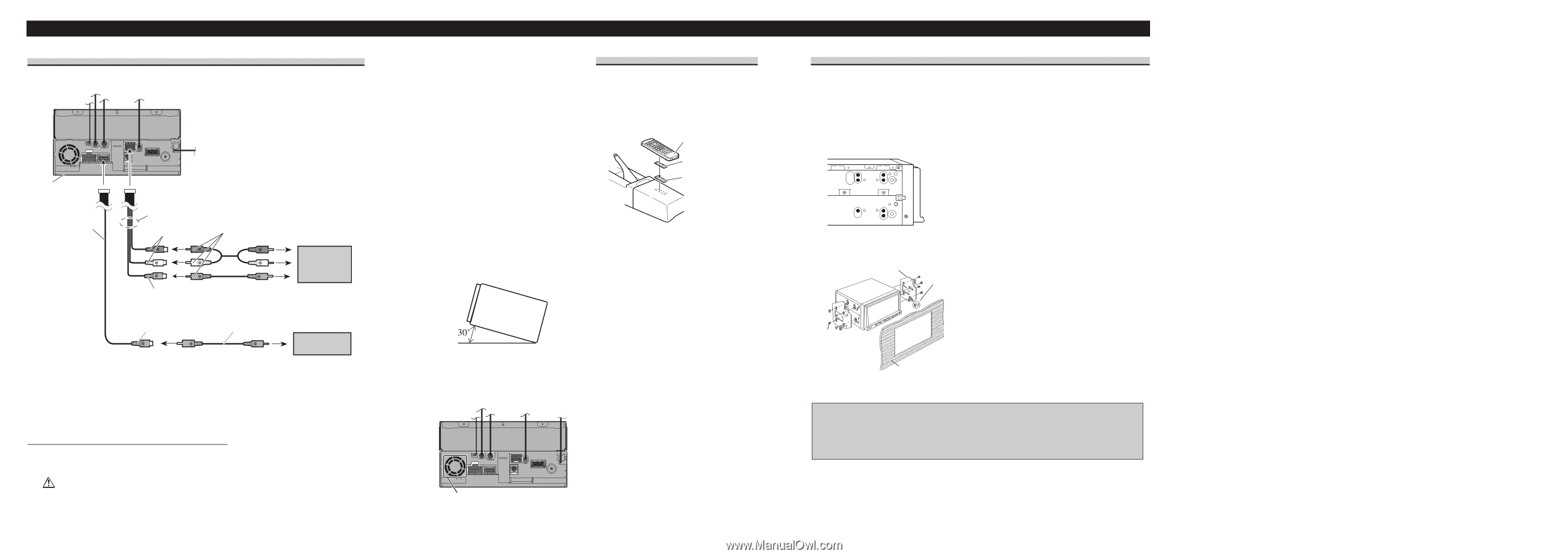
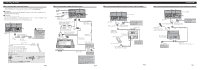
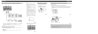
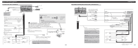
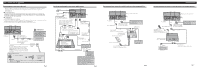
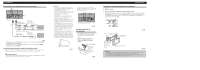
Installation When connecting the external video component and the display This product 15 cm (5-7/8 in.) 28 cm (11 in.) Audio 1 input (AUDIO 1 INPUT) RCA cables (sold separately) To audio outputs External video component (sold separately) To video output Video 1 input (VIDEO 1 INPUT) Video output (VIDEO OUTPUT) RCA cable (sold separately) To video input Display with RCA input jacks Fig. 8 • It is necessary to set AV INPUT to VIDEO on the SETUP menu when connecting to external video component. • It is necessary to set AV INPUT to EXT-V on the SETUP menu when connecting to DVD player. When using a display connected to video output This product's video output is for connection of a display to enable passengers in the rear seats to watch the DVD or Video CD. WARNING: • NEVER install the display in a location that enables the Driver to watch the DVD or Video CD while Driving. Note: • Before finally installing the unit, connect the wiring temporarily, making sure it is all connected up properly, and the unit and the system work properly. • Use only the parts included with the unit to ensure proper installation. The use of unauthorized parts can cause malfunctions. • Consult with your nearest dealer if installation requires the drilling of holes or other modifications of the vehicle. • Install the unit where it does not get in the driver's way and cannot injure the passenger if there is a sudden stop, like an emergency stop. • Do not install the display where it may (i) obstruct the driver's vision, (ii) impair the performance of any of the vehicle's operating systems or safety features, including air bags, hazard lamp buttons or (iii) impair the driver's ability to safely operate the vehicle. • The semiconductor laser will be damaged if it overheats, so don't install the unit anywhere hot - for instance, near a heater outlet. • If installation angle exceeds 30° from horizontal, the unit might not give its optimum performance. (Fig. 9) Installing the remote control unit When not using the remote control unit, secure it with velcro tape to prevent it from moving. • Thoroughly wipe off the surface before affixing the velcro tape. Remote control unit Velcro tape (small) (hard) Velcro tape (small) (soft) Fig.11 Fig. 9 • The cords must not cover up the area shown in the figure below. This is necessary to allow the amplifires to radiate freely. (Fig. 10) Leave this space. Fig. 10 Installation using the screw holes on the side of this unit 1. Remove the frame. 2. Fastening this unit to the factory radio mounting bracket. Position this unit so that the brackets screw holes and its screw holes are aligned (are fitted), and tighten the screws at 3 or 4 locations on each side. Use either the binding screws (5 mm × 6 mm) or flush surface screws (5 mm × 6 mm), depending on the shape of the bracket's screw holes. Factory radio mounting bracket If the pawl gets in the way, bend it down Fig. 12 Binding screw or flush surface screw Be sure to use the screws supplied with this product. Dashboard or console Fig. 13 Note: • In some types of automobiles, descrepancy may occur between the main unit and the dashboard. If this happens, use the supplied panel to fill the gap . • To some types of automobiles, ths unit cannot be properly installed. In such case, use the installa- tion kit ADT-VA133 (sold separately).
-
 1
1 -
 2
2 -
 3
3 -
 4
4 -
 5
5 -
 6
6 -
 7
7 -
 8
8
 |
 |