Pioneer DEH-340 Service Manual - Page 18
Parts, 2.1 Ic - clock
 |
View all Pioneer DEH-340 manuals
Add to My Manuals
Save this manual to your list of manuals |
Page 18 highlights
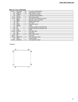
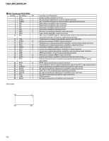
DEH-340,3400,34 7.2 PARTS 7.2.1 IC - Pin Functions(PE5262A) Pin No. Pin Name I/O 1 MODEL1 I 2,3 NC 4 AVSS I 5 ST I 6 SD I 7 AVREF1 8 KYDT I 9 DPDT O 10 SDBW I 11 TUNPDI I 12 TUNPDO O 13 TUNPCK O 14 TUNPCE O 15 currq O 16 LOCL O 17 NC 18 fm/AM O 19 NC 20 FLPILM O 21 VDCONT O 22 NC 23 CONT O 24 XCE O 25 xrst O 26 XPCK O 27-30 XPI0-3 I/O 31 CLCONT O 32 HOME I 33 VSS 34 LOEJ O 35 CD5VON O 36,37 ROT1-0 I 38 TELIN I 39 NC 40 ILMPW O 41 swvdd O 42 SYSPW O 43 VST O 44 mute O 45 PEE O 46 LOCH O 47 NC 48 TUNPCE2 O 49 PCL O 50 VCK O 51 VDT O 52 ANTPW O 53 EJECTS I 54 DALMON O 55-59 NC 60 reset I 61,62 NC 63 bsens I 64 asens I 65 dsens I 66 ADPW O 67 NC Format C C C C C C C C C C C C C C C C C C C C C C C C C C C C C C Function and Operation Model select input Not used A/D GND FM stereo input SD input A/D converter reference voltage Key data input Display data output SDBW input PLL IC data input PLL IC data output PLL IC clock output PLL IC chip enable output Tuner voltage FIX output Local L output Not used FM/AM power select output Not used Inside of flap illumination output VD control output Not used Servo driver power supply control output CD LSI chip enable output CD LSI reset output CD LSI clock output CD LSI data input/output Driver input select output Home position detector input GND CD load motor LOAD/EJECT direction exchange output CD +5V power supply control output Rotary encoder data input Telephone mute input Not used Illumination power supply control output Keyboard unit power supply control output System power supply control output Strobe pulse output for electronic volume System mute output Beep tone output Local H output Not used EEPROM chip enable output Clock adjustment output Clock output for electronic volume Data output for electronic volume Antenna output Eject key input pin Stand-by output Not used Reset input Not used Back up power sense input ACC power sense input Grille detach sense A/D converter power supply output Not used 49
-
 1
1 -
2
-
3
-
4
-
5
-
6
-
7
-
8
-
9
-
10
-
11
-
12
-
 13
13 -
 14
14 -
 15
15 -
 16
16 -
 17
17 -
 18
18 -
 19
19 -
 20
20 -
 21
21 -
 22
22 -
 23
23 -
24
-
25
-
26
-
27
-
28
-
29
-
30
-
31
-
32
-
33
-
34
-
35
-
36
-
37
 |
 |