Pioneer DEH-P4100 Operation Manual - Page 66
Cpprayer - wired remote
 |
View all Pioneer DEH-P4100 manuals
Add to My Manuals
Save this manual to your list of manuals |
Page 66 highlights
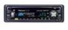
When not connecting a rear speaker lea to a subwoofer 7-~ + I ~o ~I 1. USB cable Connect to separately sold USB device. 3. Rear outF7:~:9; 2. This P~Oduct 20 cm (7-7/8 in.) 1 29. To rear output 9' 4. Front output ~l."·9 i$ . k.---r.;? 9' 5. Antenna Jac / 7SW:f= °i~::Jc;-+--- 7 Wired remote input Hard-wired rem.ote control adaptor can '" be connected (sold separately). 6. Subwoofer output 8 IP-BUS Input (Blue) 11. Fuse (10 A) [=:J \ 10.fv1UUi•Cpprayer ~ 9 IP-BUS cable (solds~par'ately) 30. To front output 31. To subwoofer output ~-'/-----4 d~ l:i..:...:o~~""""'1Ir..iI 12. Yellow Connect to the constant 12 V supply terminal. 13. Red Connect to terminal controlled by ignition switch (12 V DC). 14. Orange/white Connect to lighting switch terminal. 15. Black (chassis ground) Connect to a clean. paint-free metal location. 1 1 I 18. Gray I ~ : I 20. Front speaker ~ ~ ~ 20. Front speaker : I I I 21. Left 17. White/black 19. Gray/black I 22. Right I speaker~ ~ I : 27. Rear 23. Green 25. Violet JII c I 27 Rear speaker : I ~ ~ I I 24. Green/black 26. Violet/black I 8-~it~ : 2-s~e:k~r ~y~te~~d~ ~o~ - - - - - connect anything to the speaker leads that are not connected to speakers. 35. System remote control L , 34. Blue/white I I Connect to system control terminal of the power I amp or auto-antenna relay control terminal I (max. 300 mA 12 V DC) I I I __________ _1 36. Perform these I c_on_ne_ct_ion_s when using I the optional amplifier. I - 1 37.Subwoofer 20. Front speaker 27. Rear speaker 37.Subwoofer 20. Front speaker 27. Rear speaker
-
 1
1 -
2
-
3
-
4
-
5
-
6
-
7
-
8
-
9
-
10
-
11
-
12
-
13
-
14
-
15
-
16
-
17
-
18
-
19
-
20
-
21
-
22
-
23
-
24
-
25
-
26
-
27
-
28
-
29
-
30
-
31
-
32
-
33
-
34
-
35
-
36
-
37
-
38
-
39
-
40
-
41
-
42
-
43
-
44
-
45
-
46
-
47
-
48
-
49
-
50
-
51
-
52
-
53
-
54
-
55
-
56
-
57
-
58
-
59
-
60
-
 61
61 -
 62
62 -
 63
63 -
 64
64 -
 65
65 -
 66
66 -
 67
67 -
 68
68 -
 69
69 -
 70
70 -
 71
71 -
72
-
73
 |
 |
