Pioneer DEH-P6700MP Installation Manual - Page 2
Connecting the Units, <ENGLISH>, Installation - manual
 |
View all Pioneer DEH-P6700MP manuals
Add to My Manuals
Save this manual to your list of manuals |
Page 2 highlights
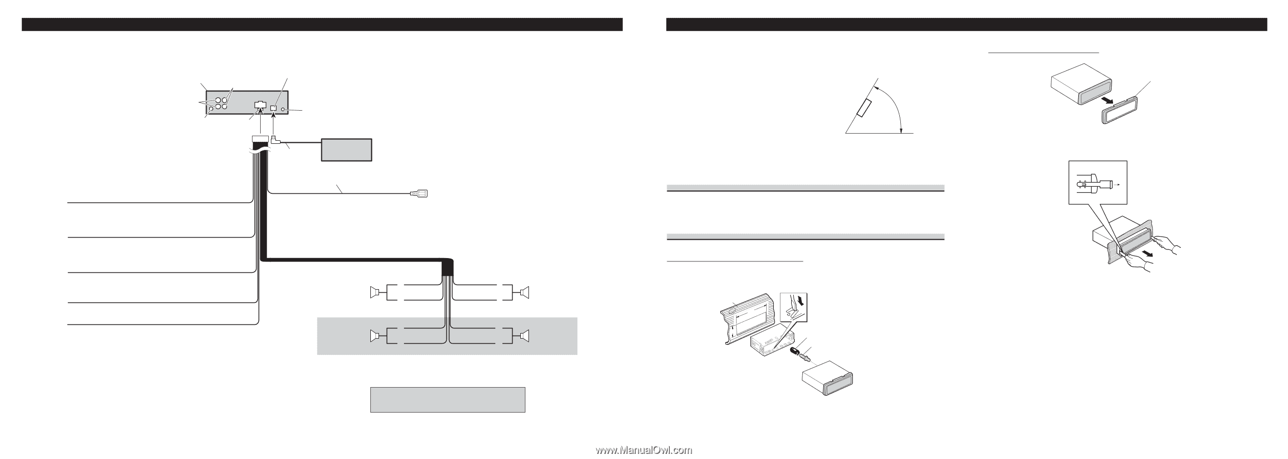
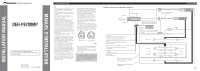
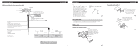
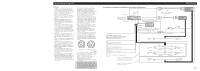
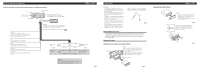
Connecting the Units 7 When using a Subwoofer without using the optional amplifier This product Front output IP-BUS input (Blue) Subwoofer output Antenna jack Fuse Jack for the Wired Remote Control Please see the Instruction Manual for the Wired Remote Control (sold separately). IP-BUS cable Multi-CD player (sold separately) Blue/white To system control terminal of the power amp or Auto-antenna relay control terminal (max. 300 mA 12 V DC). Yellow/black If you use a cellular telephone, connect it via the Audio Mute lead on the cellular telephone. If not, keep the Audio Mute lead free of any connections. Yellow To terminal always supplied with power regardless of ignition switch position. Red To electric terminal controlled by ignition switch (12 V DC) ON/OFF. Orange/white To lighting switch terminal. Black (ground) To vehicle (metal) body. Front speaker Left Subwoofer White + ≠ White/black + Green ≠ Green/black Gray Gray/black Violet Violet/black + Front speaker ≠ Right + Subwoofer ≠ Note: Change the initial setting of this unit (refer to the Operation Manual). The subwoofer output of this unit is monaural. Fig. 3 Installation Note: • Before making a final installation of the unit, tem- porarily connect the wiring to confirm that the connections are correct and the system works properly. • Use only the parts included with the unit to ensure proper installation. The use of unauthorized parts can cause malfunctions. • Consult with your nearest dealer if installation requires the drilling of holes or other modifications of the vehicle. • Install the unit where it does not get in the driver's way and cannot injure the passenger if there is a sudden stop, like an emergency stop. • The semiconductor laser will be damaged if it overheats, so don't install the unit anywhere hot - for instance, near a heater outlet. • If installation angle exceeds 60° from horizontal, the unit might not give its optimum performance. (Fig. 4) 60° Fig. 4 DIN Front/Rear-mount This unit can be properly installed either from "Front" (conventional DIN Front-mount) or "Rear" (DIN Rear-mount installation, utilizing threaded screw holes at the sides of unit chassis). For details, refer to the following illustrated installation methods. DIN Front-mount Installation with the rubber bush (Fig. 5) Dashboard 182 Holder After inserting the holder into the dashboard, then select the appropriate tabs according to the thickness of the dashboard material and bend them. (Install as firmly as possible using the top and bottom tabs. To secure, bend the tabs 90 degrees.) 53 Rubber bush Screw Fig. 5 Removing the unit (Fig. 6) (Fig. 7) Frame To remove the frame, extend top and bottom of the frame outwards in order to unlock it. (When reattaching the frame, point the side with a groove downwards and attach it.) • It becomes easy to remove the frame if the front panel is released. Fig. 6 Insert the supplied extraction keys into the unit, as shown in the figure, until they click into place. Keeping the keys pressed against the sides of the unit, pull the unit out. Fig. 7
-
 1
1 -
 2
2 -
 3
3 -
 4
4 -
 5
5 -
 6
6
 |
 |