Pioneer DMH-C2550NEX Installation Manual - Page 3
Notice for the blue, white lead, This product, Power cord - firmware
 |
View all Pioneer DMH-C2550NEX manuals
Add to My Manuals
Save this manual to your list of manuals |
Page 3 highlights
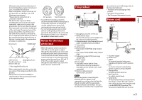
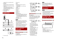
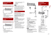
English (Maximum input power) and between 4 Ω to 8 Ω (impedance value). Do not use 1 Ω to 3 Ω speakers for this unit. • When rear speaker output is used by 2 Ω of subwoofer, use speakers over 70 W (Maximum input power). *Please refer to connection for a connection method. • The black cable is ground. When installing this unit or power amp (sold separately), make sure to connect the ground wire first. Ensure that the ground wire is properly connected to metal parts of the car's body. The ground wire of the power amp and the one of this unit or any other device must be connected to the car separately with different screws. If the screw for the ground wire loosens or falls out, it could result in fire generation of smoke or malfunction. Ground wire POWER AMP Other devices Metal parts of car's (Another electronic body device in the car) *1 Non supplied for this unit • When replacing the fuse, be sure to only use a fuse of the rating prescribed on this product. • This product cannot be installed in a vehicle without ACC (accessory) position on the ignition switch. ACC position No ACC position • To avoid short-circuiting, cover the disconnected lead with insulating tape. It is especially important to insulate all unused speaker leads, which if left uncovered may cause a short circuit. • For connecting a power amp or other devices to this product, refer to the manual for the product to be connected. • The graphical symbol placed on the product means direct current. Notice for the blue/ white lead • When the ignition switch is turned on (ACC ON), a control signal is output through the blue/white lead. Connect to an external power amp's system remote control terminal, the auto-antenna relay control terminal, or the antenna booster power control terminal (max. 300 mA 12 V DC). The control signal is output through the blue/white lead, even if the audio source is switched off. This product the activation on the followings (refer to the Operation Manual.): • The label on the packaging of this product • The label on this product • The [Firmware Information] screen Power cord Microphone 3 m (9 ft. 10-1/8 in.) Wired remote input Hard-wired remote control adapter can be connected (sold separately). iDatalink adapter (sold separately) input (DMH-C5500NEX/DMH-C2550NEX) This product Antenna jack Front output (STD)/High range output (NW) Rear output (STD)/Middle range output (NW) Subwoofer output (STD)/Low range output (NW) Power supply Fuse (10 A) SiriusXM Connect Vehicle Tuner Refer to the instruction manual for SiriusXM Connect Vehicle Tuner (sold separately). Monitor cable connector Connect to LCD screen NOTE Before using and/or connecting the iDatalink Maestro adapter (sold separately), you will need to first flash the Maestro module with the appropriate vehicle and head unit firmware. You can find the device number that is required for To power supply Power cord Yellow To terminal supplied with power regardless of ignition switch position. Red To electric terminal controlled by ignition switch (12 V DC) ON/OFF Orange/white To lighting switch terminal. Black (ground) To vehicle (metal) body. Violet/white Of the two lead wires connected to the back lamp, connect the one in which the voltage changes when the gear shift is in the REVERSE (R) position. This connection enables the unit to sense En 3
-
 1
1 -
 2
2 -
 3
3 -
 4
4 -
 5
5 -
 6
6 -
 7
7 -
 8
8 -
 9
9 -
10
-
11
-
12
-
13
-
14
-
15
-
16
-
17
-
18
-
19
-
20
-
21
-
22
-
23
-
24
-
25
-
26
-
27
-
28
 |
 |
