Pioneer GM-5500T Owner's Manual
Pioneer GM-5500T Manual
 |
View all Pioneer GM-5500T manuals
Add to My Manuals
Save this manual to your list of manuals |
Pioneer GM-5500T manual content summary:
- Pioneer GM-5500T | Owner's Manual - Page 1
English Français Owner's Manual Mode d'emploi BRIDGEABLE TWO-CHANNEL POWER AMPLIFIER AMPLIFICATEUR DE PUISSANCE PONTABLE À DEUX CANAUX AMPLIFICADOR DE POTENCIA DE DOS CANALES EN PUENTE GM-5500T Español - Pioneer GM-5500T | Owner's Manual - Page 2
manual. Please keep the manual in a safe and accessible place for future reference. Information to User Alteration or modifications carried out without appropriate authorization may invalidate the user's right to operate the equipment. After-sales service for Pioneer Download owner's manuals, set the - Pioneer GM-5500T | Owner's Manual - Page 3
operate in the conditions outlined below. If the Protection function is turned on, the power indicator will turn off, and the amplifier will shut down. ! If the speaker output terminal and speaker wire is short-circuited. ! If the temperature inside the amplifier gets too high. ! If a DC voltage is - Pioneer GM-5500T | Owner's Manual - Page 4
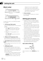
! For use with an RCA equipped car stereo (standard output of 500 mV), set to the NORMAL position. For use with an RCA equipped Pioneer car stereo, with max. Setting gain properly ! Protective function included to prevent malfunction of the unit and/or speakers due to excessive output, improper use - Pioneer GM-5500T | Owner's Manual - Page 5
Setting the unit Relationship between amplifier gain and head unit output power If amplifier gain is raised improperly, this will simply increase distortion, with little increase in power. Signal waveform when outputting at high volume using amplifier gain control Signal waveform distorted with high - Pioneer GM-5500T | Owner's Manual - Page 6
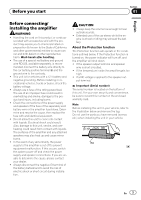
control terminal of the car stereo. Before connecting the amplifier WARNING ! Secure the wiring with cable clamps or adhe- sive tape. To protect the wiring, wrap sections in contact with metal parts in adhesive tape. ! Never cut the insulation of the power supply to feed power to other equipment - Pioneer GM-5500T | Owner's Manual - Page 7
amplifiers, please follow the speaker output connection diagram for bridging shown on rear: two 8 W speakers in parallel for a 4 W load or a single 4 W speaker per channel. For any further enquiries, contact your local authorized Pioneer dealer or customer service. About suitable specification - Pioneer GM-5500T | Owner's Manual - Page 8
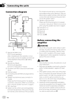
speaker input wire. ! Do not connect both the RCA input and the speaker input at the same time. of the amplifier to the positive (+) battery terminal. 1 Car Stereo 2 Speaker output 3 White/black: Left * 4 White: Left + 5 Gray/black: Right * 6 Gray: Right + 7 Speaker input connector To speaker - Pioneer GM-5500T | Owner's Manual - Page 9
1 System remote control terminal 2 Ground terminal 3 Power terminal 4 Terminal screws 5 Battery wire 6 Ground wire 7 System remote control wire Connecting the speaker output terminals 1 Use wire cutters or a utility knife to strip the end of the speaker wires to expose about 10 mm (3/8 in.) of - Pioneer GM-5500T | Owner's Manual - Page 10
of the car, which can result in fire. ! Make sure that wires do not get caught in the sliding mechanism of the seats or touch the legs of a person in the vehicle as short-circuit may result. ! When drilling to install the amplifier, always confirm no parts are behind the panel and protect all cables - Pioneer GM-5500T | Owner's Manual - Page 11
Level 0 dB/6 dB/12 dB Gain control: RCA 200 mV to 6.5 V Speaker 0.8 V to 26 V Maximum input level / impedance: RCA 6.5 V / 22 kW Speaker 26 V / 22 kW CEA2006 Specifications Power output 125 W RMS × 2 Channels (at 14.4 V, 4 W and ≦ 1 % THD+N) S/N ratio 78 dBA (reference: 1 W into 4 W) Notes - Pioneer GM-5500T | Owner's Manual - Page 12
Pioneer Electronics (USA) Inc. CUSTOMER SUPPORT DIVISION P.O. Box 1760 Long Beach, CA 90801-1760 800-421-1404 CANADA Pioneer Électroniques du Canada, Inc. Département de service les modes d'emploi, commandez les catalogues des produits, recherchez de nouveaux produits, et bien plus. La protection de - Pioneer GM-5500T | Owner's Manual - Page 13
à la masse du négatif. Vérifiez la tension de la batterie avant l'installation dans des véhicules de caravaning, des camions ou des bus. ! Utilisez -dessous. Si la fonction de protection est activée, l'indicateur de mise sous tension s'éteint et l'amplificateur se met hors service. ! Si la borne de - Pioneer GM-5500T | Owner's Manual - Page 14
Section 01 Avant de commencer Remarque Avant d'installer cet appareil dans votre voiture, reportez-vous à l'illustration ci-dessous et retirez cette cosse. N'utilisez pas les pièces que vous avez retirées (vis, etc.) lors de l'installation de l'appareil dans votre voiture. 14 Fr - Pioneer GM-5500T | Owner's Manual - Page 15
). Pour l'utilisation avec un système stéréo de véhicule Pioneer équipé d'une sortie RCA, dont la sortie maximale est correct du gain ! Fonction de protection incluse pour éviter tout dysfonctionnement de é au niveau de sortie maximal de la sortie préamp de l'appareil central de manière à ce que - Pioneer GM-5500T | Owner's Manual - Page 16
rement coupé alors que les réglages du gain et du volume sont corrects. Dans de tels cas, veuillez contacter le Centre d'entretien agréé par Pioneer le plus proche. Commande de gain de l'appareil L'illustration ci-dessus représente le réglage de gain NORMAL. Relation entre le gain de l'amplificateur - Pioneer GM-5500T | Owner's Manual - Page 17
des haut-parleurs Veuillez vous reporter à la section suivante pour les instructions de connexion des hautparleurs. Reportez-vous à la page 19, Connexions ! Ne raccourcissez jamais aucun fil, faute de quoi le circuit de protection risque de fonctionner de manière incorrecte. ! Ne mettez jamais le - Pioneer GM-5500T | Owner's Manual - Page 18
syntoniseur. À propos du mode ponté Pour toute autre requête, veuillez contacter le service clientèle ou votre revendeur Pioneer agréé local. À propos Sortie deux canaux Entrée max. : 250 W min. Sortie un canal Entrée max. : 800 W min. Connexion des haut-parleurs Le mode de sortie des haut- - Pioneer GM-5500T | Owner's Manual - Page 19
Connexion des appareils Sortie deux canaux (stéréo) Section 03 Français 1 2 1 Haut-parleur (gauche) 2 Haut-parleur (droit) Sortie un canal 1 Système stéréo du véhicule 2 Sortie des haut-parleurs 3 Blanc/noir : * gauche 4 Blanc : + gauche 5 Gris/noir : * droite 6 Gris : + droite 7 Connecteur d' - Pioneer GM-5500T | Owner's Manual - Page 20
Section 03 Connexion des appareils 1 Borne positive (+) 2 Compartiment du moteur 3 Intérieur du véhicule 4 Fusible (30 A) × 2 5 Insérez la rondelle en caoutchouc du joint torique dans la carrosserie du véhicule. 6 Percez un trou de 14 mm dans la carrosse- rie du véhicule. 2 Torsadez le fil de la - Pioneer GM-5500T | Owner's Manual - Page 21
Connexion des appareils 1 Cosse (vendue séparément) 2 Fil du haut-parleur 3 Connectez les fils des haut-parleurs aux bornes de sortie des haut-parleurs. Fixez fermement les fils des haut-parleurs à l'aide des vis de la borne. 1 Vis de la borne 2 Fils des haut-parleurs 3 Bornes de sortie des haut- - Pioneer GM-5500T | Owner's Manual - Page 22
pas les jambes d'un passager, car cela pourrait entraîner un court-circuit. ! Lorsque vous percez pour installer l'amplificateur, vérifiez toujours qu'il La fonction de protection peut s'activer afin de protéger l'amplificateur contre une surchauffe causée par une installation dans un emplace - Pioneer GM-5500T | Owner's Manual - Page 23
Installation 3 Installez l'amplificateur à l'aide des vis autotaraudeuses fournies (4 mm × 18 mm). 1 Vis autotaraudeuses (4 mm × 18 mm) 2 Percez un trou de 2,5 mm de diamètre. 3 Tapis de sol ou châssis Français Section 04 Fr 23 - Pioneer GM-5500T | Owner's Manual - Page 24
un canal) Fusible 25 A × 2 Dimensions (L × H × P) ...... 289 mm 349 mm Poids 3,2 kg (fils de câblage non inclus) Puissance de sortie maximale 820 W (410 W × 2) Puissance de sortie continue 125 W × 2 (à 14 kW Caractéristiques CEA2006 Puissance de sortie 125 W RMS × 2 canaux (à 14,4 V, 4 W et - Pioneer GM-5500T | Owner's Manual - Page 25
UU. Pioneer Electronics (USA) Inc. CUSTOMER SUPPORT DIVISION P.O. Box 1760 Long Beach, CA 90801-1760 800-421-1404 CANADÁ Pioneer Electronics actualizados sobre los últimos productos y tecnologías. 3 Descargue manuales de instrucciones, solicite catálogos de productos, busque nuevos productos - Pioneer GM-5500T | Owner's Manual - Page 26
durante la instalación. Nota Antes de instalar esta unidad en su vehículo, refiérase a la ilustración abajo y quite la pieza. No utilice las partes retiradas (tornillos, etc.) al instalar la unidad en su vehículo. PRECAUCIÓN ! Mantenga siempre el volumen lo suficiente- mente bajo como para poder - Pioneer GM-5500T | Owner's Manual - Page 27
la unidad Sección 02 Español Qué es cada cosa Parte delantera Parte trasera Para ajustar el interruptor, si es preciso utilice un de 500 mV), posiciónese en NORMAL. Para el uso con un estéreo de vehículo Pioneer provisto de RCA, con una salida máxima de 4 V o superior, ajuste el nivel para que - Pioneer GM-5500T | Owner's Manual - Page 28
Sección 02 Configuración de la unidad Control de ganancia de esta unidad La imagen anterior muestra un ajuste de ganancia NORMAL. Relación entre ganancia del amplificador y corriente de salida de la unidad principal Si la ganancia del amplificador se aumenta incorrectamente, sólo incrementará la - Pioneer GM-5500T | Owner's Manual - Page 29
ón del altavoz. Consulte Conexiones al utilizar el cable de entrada del altavoz en la página 31. a Fusible (25 A) × 2 b Fusible (30 A) × 2 c Ojal d Parte trasera e Parte delantera Español 1 Cable de batería rojo especial RD-223 (se vende por separado) Tras completar el resto de conexiones del - Pioneer GM-5500T | Owner's Manual - Page 30
al ralentí. ! Instale y pase el cable de la batería (adquirido por separado) lo más lejos posible de los cables del altavoz. Instale y pase el cable en puente Para cualquier otra consulta, contacte con el distribuidor oficial de Pioneer o diríjase al servicio de atención al cliente. Acerca de - Pioneer GM-5500T | Owner's Manual - Page 31
Conexión de las unidades Salida de dos canales (estéreo) Sección 03 Español 1 2 1 Altavoz (izquierdo) 2 Altavoz (derecho) Salida de un canal 1 Estéreo del vehículo 2 Salida del altavoz 3 Blanco/negro: Izquierdo * 4 Blanco: Izquierdo + 5 Gris/negro: Derecho * 6 Gris: Derecho + 7 Conector de - Pioneer GM-5500T | Owner's Manual - Page 32
Sección 03 Conexión de las unidades 1 Terminal positivo (+) 2 Compartimento del motor 3 Interior del vehículo 4 Fusible (30 A) × 2 5 Inserte el ojal elástico de la junta tórica en la carrocería. 6 Perfore un agujero de 14 mm (1/2 pulg.) en el vehículo. 2 Introduzca el cable de la batería, el de - Pioneer GM-5500T | Owner's Manual - Page 33
Conexión de las unidades 1 Lengüeta (se vende por separado) 2 Cable del altavoz 3 Conecte los cables del altavoz a los terminales de salida del altavoz. Fije los cables del altavoz firmemente utilizando los tornillos para terminales. 1 Tornillos para terminales 2 Cables del altavoz 3 Terminales de - Pioneer GM-5500T | Owner's Manual - Page 34
instalación correcta, utili- ce las piezas facilitadas del modo indicado. El uso de otras piezas diferentes a las facilitadas, puede dañar las partes internas del amplificador o aflojarse haciendo que éste se apague. ! No instalar en: - Lugares donde pueda lesionar al conduc- tor o a los pasajeros - Pioneer GM-5500T | Owner's Manual - Page 35
Instalación 3 Instale el amplificador utilizando los tornillos con rosca cortante facilitados (4 mm × 18 mm). 1 Tornillos de rosca cortante (4 mm × 18 mm) 2 Perfore un orificio de 2,5 mm de diámetro 3 Moqueta o chasis del automóvil Español Sección 04 Es 35 - Pioneer GM-5500T | Owner's Manual - Page 36
mm × 62 mm × 349 mm Peso 3,2 kg (conectores para cableado no incluidos) Potencia de salida máxima 820 W (410 W × 2) Potencia de salida continua 125 W × 2 (a 14,4 V, 4 W, 20 kW Altavoz 26 V / 22 kW Especificaciones CEA2006 Potencia de salida 125 W RMS × 2 canales (a 14,4 V, 4 W y ≦ 1 % THD+N) - Pioneer GM-5500T | Owner's Manual - Page 37
Español Es 37 - Pioneer GM-5500T | Owner's Manual - Page 38
38 Es - Pioneer GM-5500T | Owner's Manual - Page 39
Español Es 39 - Pioneer GM-5500T | Owner's Manual - Page 40
ELECTRONICS OF CANADA, INC. 340 Ferrier Street, Unit 2, Markham, Ontario L3R 2Z5, Canada TEL: 1-877-283-5901 TEL: 905-479-4411 PIONEER ELECTRONICS DE MEXICO, S.A. de C.V. Blvd.Manuel Avila Camacho 138 10 piso Col.Lomas de Chapultepec, Mexico, D.F. 11000 TEL: 55-9178-4270 407號8 02) 2657-3588
-
 1
1 -
 2
2 -
 3
3 -
 4
4 -
 5
5 -
 6
6 -
 7
7 -
8
-
9
-
10
-
11
-
12
-
13
-
14
-
15
-
16
-
17
-
18
-
19
-
20
-
21
-
22
-
23
-
24
-
25
-
26
-
27
-
28
-
29
-
30
-
31
-
32
-
33
-
34
-
35
-
36
-
37
-
38
-
39
-
40
 |
 |

Owner
’
s Manual
Mode d
’
emploi
BRIDGEABLE TWO-CHANNEL POWER AMPLIFIER
AMPLIFICATEUR DE PUISSANCE PONTABLE À
DEUX CANAUX
AMPLIFICADOR DE POTENCIA DE DOS CANALES
EN PUENTE
GM-5500T
English
Español
Français