Pioneer GM-5500T Owner's Manual - Page 11

Specifications, Additional information - rms

Page 11 highlights

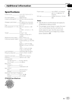
Additional information Appendix English Specifications Power source 14.4 V DC (10.8 V to 15.1 V allowable) Grounding system Negative type Current consumption 29 A (at continuous power, 4 W) Average current drawn ......... 8 A (4 W for two channels) 14 A (4 W for one channel) Fuse 25 A × 2 Dimensions (W × H × D) ... 289 mm × 62 mm × 349 mm (11-3/8 in. ×2-1/2 in. × 1 ft. 2 in.) Weight 3.2 kg (7.1 lbs) (Leads for wiring not included) Maximum power output ....... 820 W (410 W × 2) Continuous power output ... 125 W × 2 (at 14.4 V, 4 W, 20 Hz to 20 kHz, ≦ 1.0 % THD +N) 400 W × 1 (at 14.4 V, 4 W BRIDGE 1 kHz, ≦ 1.0 % THD +N) 190 W × 2 (at 14.4 V, 2 W, 1 kHz, ≦ 1.0 % THD+N) Load impedance 4 W (2 W to 8 W allowable) Frequency response 10 Hz to 70 kHz (+0 dB, - 3 dB) Signal-to-noise ratio 98 dB (IHF-A network) Distortion 0.05 % (10 W, 1 kHz) Low pass filter: Cut off frequency 40 Hz to 500 Hz Cut off slope 12 dB/oct Bass boost: Frequency 50 Hz Level 0 dB/6 dB/12 dB Gain control: RCA 200 mV to 6.5 V Speaker 0.8 V to 26 V Maximum input level / impedance: RCA 6.5 V / 22 kW Speaker 26 V / 22 kW CEA2006 Specifications Power output 125 W RMS × 2 Channels (at 14.4 V, 4 W and ≦ 1 % THD+N) S/N ratio 78 dBA (reference: 1 W into 4 W) Notes ! Specifications and the design are subject to modifications without notice. ! The average current drawn is nearly the maxi- mum current drawn by this unit when an audio signal is input. Use this value when working out total current drawn by multiple power amplifiers. En 11

  • 1
  • 2
  • 3
  • 4
  • 5
  • 6
  • 7
  • 8
  • 9
  • 10
  • 11
  • 12
  • 13
  • 14
  • 15
  • 16
  • 17
  • 18
  • 19
  • 20
  • 21
  • 22
  • 23
  • 24
  • 25
  • 26
  • 27
  • 28
  • 29
  • 30
  • 31
  • 32
  • 33
  • 34
  • 35
  • 36
  • 37
  • 38
  • 39
  • 40

Specifications
Power source
.............................
14.4 V DC (10.8 V to 15.1 V
allowable)
Grounding system
...................
Negative type
Current consumption
............
29 A (at continuous power,
4
W
)
Average current drawn
.........
8 A (4
W
for two channels)
14 A (4
W
for one channel)
Fuse
................................................
25 A × 2
Dimensions (W × H × D)
...
289 mm × 62 mm × 349
mm
(11-3/8 in. ×2-1/2 in. × 1 ft.
2 in.)
Weight
..........................................
3.2 kg (7.1 lbs)
(Leads for wiring not in-
cluded)
Maximum power output
.......
820 W (410 W × 2)
Continuous power output
...
125 W × 2 (at 14.4 V, 4
W
,
20 Hz to 20 kHz,
1.0 % THD
+N)
400 W × 1 (at 14.4 V, 4
W
BRIDGE 1 kHz,
1.0 % THD
+N)
190 W × 2 (at 14.4 V, 2
W
,
1 kHz,
1.0 % THD+N)
Load impedance
......................
4
W
(2
W
to 8
W
allowable)
Frequency response
...............
10 Hz to 70 kHz (+0 dB,
3 dB)
Signal-to-noise ratio
...............
98 dB (IHF-A network)
Distortion
.....................................
0.05 % (10 W, 1 kHz)
Low pass filter:
Cut off frequency
...........
40 Hz to 500 Hz
Cut off slope
.....................
12 dB/oct
Bass boost:
Frequency
..........................
50 Hz
Level
.....................................
0 dB/6 dB/12 dB
Gain control:
RCA
......................................
200 mV to 6.5 V
Speaker
..............................
0.8 V to 26 V
Maximum input level / impedance:
RCA
......................................
6.5 V / 22 k
W
Speaker
..............................
26 V / 22 k
W
CEA2006 Specifications
Power output
.............................
125 W RMS × 2 Channels
(at 14.4 V, 4
W
and
1%
THD+N)
S/N ratio
.......................................
78 dBA (reference: 1 W into
4
W
)
Notes
!
Specifications and the design are subject to
modifications without notice.
!
The average current drawn is nearly the maxi-
mum current drawn by this unit when an
audio signal is input. Use this value when
working out total current drawn by multiple
power amplifiers.
En
11
English
Appendix
Additional information