Pioneer GM-5500T Owner's Manual - Page 9
Connecting the speaker, output terminals, Connecting the units
 |
View all Pioneer GM-5500T manuals
Add to My Manuals
Save this manual to your list of manuals |
Page 9 highlights
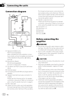
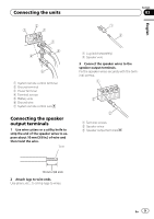
Connecting the units Section 03 English 1 System remote control terminal 2 Ground terminal 3 Power terminal 4 Terminal screws 5 Battery wire 6 Ground wire 7 System remote control wire Connecting the speaker output terminals 1 Use wire cutters or a utility knife to strip the end of the speaker wires to expose about 10 mm (3/8 in.) of wire and then twist the wire. Twist 1 Lug (sold separately) 2 Speaker wire 3 Connect the speaker wires to the speaker output terminals. Fix the speaker wires securely with the terminal screws. 1 Terminal screws 2 Speaker wires 3 Speaker output terminals 2 Attach lugs to wire ends. Use pliers, etc., to crimp lugs to wires. En 9
-
 1
1 -
2
-
3
-
 4
4 -
 5
5 -
 6
6 -
 7
7 -
 8
8 -
 9
9 -
 10
10 -
 11
11 -
 12
12 -
 13
13 -
 14
14 -
15
-
16
-
17
-
18
-
19
-
20
-
21
-
22
-
23
-
24
-
25
-
26
-
27
-
28
-
29
-
30
-
31
-
32
-
33
-
34
-
35
-
36
-
37
-
38
-
39
-
40
 |
 |

1
System remote control terminal
2
Ground terminal
3
Power terminal
4
Terminal screws
5
Battery wire
6
Ground wire
7
System remote control wire
Connecting the speaker
output terminals
1
Use wire cutters or a utility knife to
strip the end of the speaker wires to ex-
pose about 10 mm (3/8 in.) of wire and
then twist the wire.
Twist
2
Attach lugs to wire ends.
Use pliers, etc., to crimp lugs to wires.
1
Lug (sold separately)
2
Speaker wire
3
Connect the speaker wires to the
speaker output terminals.
Fix the speaker wires securely with the term-
inal screws.
1
Terminal screws
2
Speaker wires
3
Speaker output terminals
En
9
English
Section
03
Connecting the units