Pioneer GM6400F Owner's Manual - Page 11
Connecting the power, terminal, Connecting the units - fix
 |
UPC - 012562912356
View all Pioneer GM6400F manuals
Add to My Manuals
Save this manual to your list of manuals |
Page 11 highlights
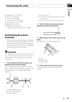
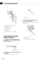
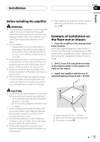
Connecting the units Section 03 English 5 Gray/black: CH A, Right * 6 Gray: CH A, Right + 7 Violet: CH B, Right + 8 Violet/black: CH B, Right * 9 Green/black: CH B, Left * a Green: CH B, Left + b Speaker input connector To speaker input terminal of this unit. 4 Fuse (30 A) × 2 5 Insert the O-ring rubber grommet into the vehicle body. 6 Drill a 14 mm hole into the vehicle body. 2 Twist the battery wire, ground wire and system remote control wire. Twist Connecting the power terminal ! The use of a special red battery and ground wire RD-223, available separately, is recommended. Connect the battery wire directly to the car battery positive terminal (+) and the ground wire to the car body. 3 Attach lugs to wire ends. Lugs not supplied. Use pliers, etc., to crimp lugs to wires. WARNING If the battery wire is not securely fixed to the terminal using the terminal screws, there is a risk of overheating, malfunction and injury, including minor burns. 1 Route battery wire from engine compartment to the vehicle interior. After completing all other amplifier connections, finally connect the battery wire terminal of the amplifier to the positive (+) battery terminal. 1 Lug 2 Battery wire 3 Ground wire 4 Connect the wires to the terminal. Fix the wires securely with the terminal screws. 1 Positive (+) terminal 2 Engine compartment 3 Vehicle interior En 11
-
 1
1 -
2
-
3
-
4
-
5
-
 6
6 -
 7
7 -
 8
8 -
 9
9 -
 10
10 -
 11
11 -
 12
12 -
 13
13 -
 14
14 -
 15
15 -
 16
16 -
17
-
18
-
19
-
20
-
21
-
22
-
23
-
24
-
25
-
26
-
27
-
28
-
29
-
30
-
31
-
32
-
33
-
34
-
35
-
36
-
37
-
38
-
39
-
40
-
41
-
42
-
43
-
44
-
45
 |
 |
