Pioneer GM6400F Owner's Manual - Page 14
Specifications, Additional information, CEA2006 Specifications - 4 channel power amplifier
 |
UPC - 012562912356
View all Pioneer GM6400F manuals
Add to My Manuals
Save this manual to your list of manuals |
Page 14 highlights
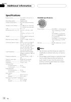
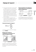
Appendix Additional information Specifications Power source 14.4 V DC (10.8 V to 15.1 V allowable) Grounding system Negative type Current consumption 35 A (at continuous power, 4 W) Average current drawn ......... 9 A (4 W for four channels) 15 A (4 W for two channels) Fuse 25 A × 2 Dimensions (W × H × D) ... 265 mm × 62 mm × 346 mm (10-3/8 in. ×2-1/2 in. × 1 ft. 2 in.) Weight 3.8 kg (Leads for wiring not included) Maximum power output ....... 120 W × 4 (4 W) / 300 W × 2 (4 W) Continuous power output ... 60 W × 4 (at 14.4 V, 4 W, 20 Hz to 20 kHz 0.2% THD) 150 W × 2 (at 14.4 V, 4 W, 20 Hz to 20 kHz 0.8% THD) 75 W × 4 (at 14.4 V, 2 W, 20 Hz to 20 kHz 0.8% THD) Load impedance 4 W (2 W to 8 W allowable) (Bridge connection: 4 W to 8 W allowable) Frequency response 10 Hz to 50 kHz (+0 dB, -1 dB) Signal-to-noise ratio 95 dB (IHF-A network) Distortion 0.03 % (10 W, 1 kHz) Separation 70 dB (1 kHz) Low pass filter: Cut off frequency 80 Hz Cut off slope 12 dB/oct High pass filter: Cut off frequency 80 Hz Cut off slope 12 dB/oct Gain control: RCA 200 mV to 6.5 V Speaker 0.8 V to 26 V Maximum input level / impedance: RCA 6.5 V / 22 kW Speaker 26 V / 90 kW CEA2006 Specifications Power output 60 W RMS × 4 Channels (at 14.4 V, 4 W and ≦ 1 % THD +N) 150 W RMS × 2 Channels (at 14.4 V, 4 W BRIDGE and ≦ 1 % THD+N) 75 W RMS × 4 Channels (at 14.4 V, 2 W and ≦ 1 % THD +N) S/N ratio 80 dBA (reference: 1 W into 4 W) Notes ! Specifications and the design are subject to modifications without notice due to improvements. ! The average current drawn is nearly the maximum current drawn by this unit when an audio signal is input. Use this value when working out total current drawn by multiple power amplifiers. 14 En
-
 1
1 -
2
-
3
-
4
-
5
-
6
-
7
-
8
-
 9
9 -
 10
10 -
 11
11 -
 12
12 -
 13
13 -
 14
14 -
 15
15 -
 16
16 -
 17
17 -
 18
18 -
 19
19 -
20
-
21
-
22
-
23
-
24
-
25
-
26
-
27
-
28
-
29
-
30
-
31
-
32
-
33
-
34
-
35
-
36
-
37
-
38
-
39
-
40
-
41
-
42
-
43
-
44
-
45
 |
 |