Pioneer IS-21T Service Manual - Page 22
Playback Recording
 |
View all Pioneer IS-21T manuals
Add to My Manuals
Save this manual to your list of manuals |
Page 22 highlights
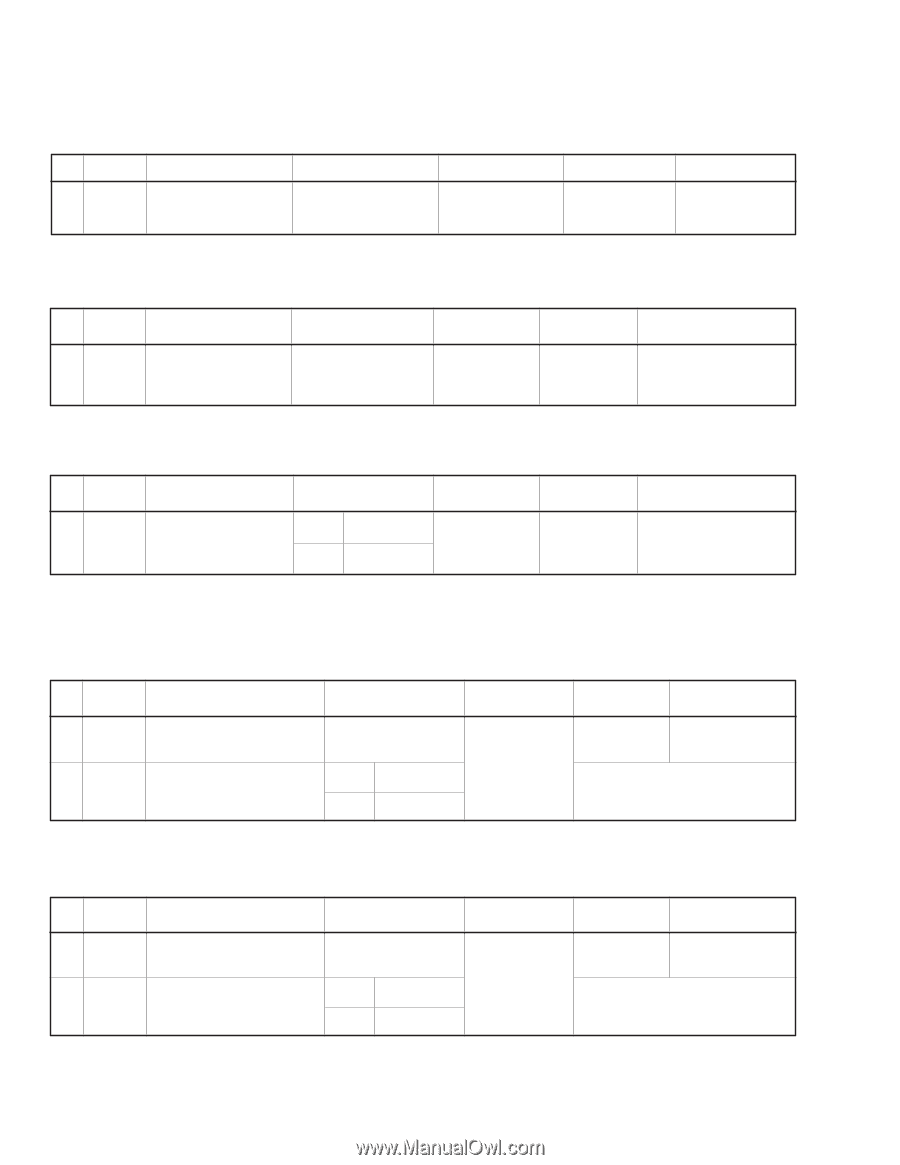
XC-IS21T 6.1.2 Playback Section (1) Tape Speed Confirmation No. Mode Input Signal/Test Tape 1 PLAY NCT-111 (3 kHz) Adjustment Points VR2701 (DECK ASSY) (Refer to Fig. 6-3) Measurement Points Adjustment Value Remarks TP R (C2204) (DECK ASSY) 3000 Hz +10 -10 Hz FWD adjustment REV Confirmation ( 3000 Hz +60 -60 Hz ) (2) Head Azimuth Adjustment ¶ This unit is equipped with auto tape selector. ¶ Do not switch between forward and reverse operation with the screwdriver inserted. No. Mode Input Signal/Test Tape Adjustment Points Measurement Points Adjustment Value Remarks 1 PLAY STD-331E test tape (Playback: 10 kHz, -20 dB) Head azimuth adjustment Screw (Refer to Fig. 6-3) TP L (C2203) TP R (C2204) (DECK ASSY) Max. Playback signal level After adjustment, apply silicon bond to the head azimuth adjustment screw. (3) Playback Level Adjustment ¶ Since this adjustment determines playback DolbyNR level, Perform it carefully. No. Mode Input Signal/Test Tape Adjustment Points Measurement Points 1 PLAY STD-331E test tape L ch (Playback: 315 Hz, 0 dB) R ch VR2301 VR2302 TP L (C2203) TP R (C2204) (DECK ASSY) Adjustment Value -3.7 dBV Remarks 6.1.3 Recording Section (1) Recording Bias Adjustment ¶ After the adjustment, caution should be exercised so as not to become under bias by checking the distortion rate. No. Mode Input Signal/Test Tape Adjustment Points Measurement Points Adjustment Value Remarks 1 REC/ Input a 315Hz signal to the LINE - PAUSE IN terminal. ∗ Input signal level Load the STD-632 test tape and L ch 2 REC = record/playback the 315Hz and PLAY 10kHz signals. (see the Note below) R ch VR2801 VR2802 TP L (C2203) TP R (C2204) (DECK ASSY) -23.7 dBV Repeat adjustment until playback level of the 10kHz signal is within 0.5dBV ±0.5dB from that of the 315Hz signal. Note: Set the 10kHz input signal level to the same value as the 315Hz input signal level of step 1. (2) Recording Level Adjustment No. Mode Input Signal/Test Tape Adjustment Points 1 REC/ Input a 315Hz signal to the LINE- PAUSE IN terminal.∗ Input signal level 2 REC = PLAY STD-632 test tape and record/ playback the 315Hz signal. L ch R ch VR2401 VR2402 Measurement Points TP L (C2203) TP R (C2204) (DECK ASSY) Adjustment Value -7.7 dBV Remarks Repeat recording, playback and adjustment until playback level of the 315Hz signal becomes -7.7dBV±0.5dB. 52
-
 1
1 -
2
-
3
-
4
-
5
-
6
-
7
-
8
-
9
-
10
-
11
-
12
-
13
-
14
-
15
-
16
-
 17
17 -
 18
18 -
 19
19 -
 20
20 -
 21
21 -
 22
22 -
 23
23 -
 24
24
 |
 |