Pioneer MVH-S400BT Owners Manual - Page 45
This unit
 |
View all Pioneer MVH-S400BT manuals
Add to My Manuals
Save this manual to your list of manuals |
Page 45 highlights
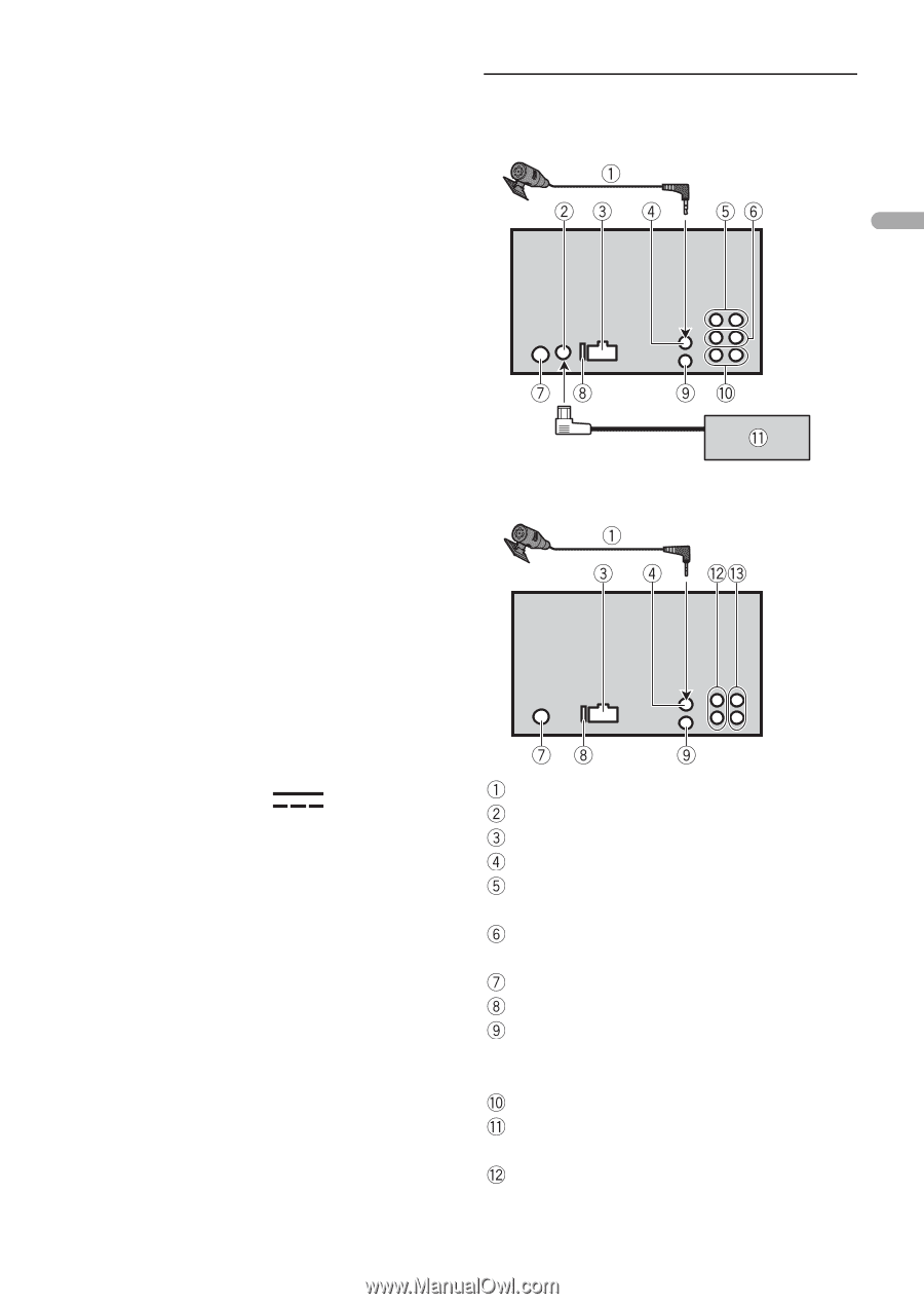
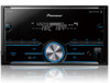
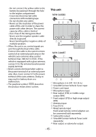
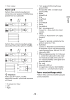
English - Do not connect the yellow cable to the battery by passing it through the hole to the engine compartment. - Cover any disconnected cable connectors with insulating tape. - Do not shorten any cables. - Never cut the insulation of the power cable of this unit in order to share the power with other devices. The current capacity of the cable is limited. - Use a fuse of the rating prescribed. - Never wire the negative speaker cable directly to ground. - Never band together negative cables of multiple speakers. • When this unit is on, control signals are sent through the blue/white cable. Connect this cable to the system remote control of an external power amp or the vehicle's auto-antenna relay control terminal (max. 300 mA 12 V DC). If the vehicle is equipped with a glass antenna, connect it to the antenna booster power supply terminal. • Never connect the blue/white cable to the power terminal of an external power amp. Also, never connect it to the power terminal of the auto antenna. Doing so may result in battery drain or a malfunction. • The graphical symbol placed on the product means direct current. This unit MVH-S600BS MVH-S400BT Microphone 3 m (9 ft. 10-1/8 in.) SiriusXM Connect Vehicle Tuner input Power cord input Microphone input Rear output (STD) or middle range output (NW) Front output (STD) or high range output (NW) Antenna input Fuse (10 A) Wired remote input Hard-wired remote control adapter can be connected (sold separately). Subwoofer output SiriusXM Connect Vehicle Tuner (sold separately) Rear output or subwoofer output - 45 -
-
 1
1 -
2
-
3
-
4
-
5
-
6
-
7
-
8
-
9
-
10
-
11
-
12
-
13
-
14
-
15
-
16
-
17
-
18
-
19
-
20
-
21
-
22
-
23
-
24
-
25
-
26
-
27
-
28
-
29
-
30
-
31
-
32
-
33
-
34
-
35
-
36
-
37
-
38
-
39
-
 40
40 -
 41
41 -
 42
42 -
 43
43 -
 44
44 -
 45
45 -
 46
46 -
 47
47 -
 48
48 -
 49
49 -
 50
50 -
51
-
52
-
53
-
54
-
55
-
56
-
57
-
58
-
59
-
60
-
61
-
62
-
63
-
64
-
65
-
66
-
67
-
68
-
69
-
70
-
71
-
72
-
73
-
74
-
75
-
76
-
77
-
78
-
79
-
80
-
81
-
82
-
83
-
84
-
85
-
86
-
87
-
88
-
89
-
90
-
91
-
92
-
93
-
94
-
95
-
96
-
97
-
98
-
99
-
100
-
101
-
102
-
103
-
104
-
105
-
106
-
107
-
108
-
109
-
110
-
111
-
112
-
113
-
114
-
115
-
116
-
117
-
118
-
119
-
120
-
121
-
122
-
123
-
124
-
125
-
126
-
127
-
128
-
129
-
130
-
131
-
132
-
133
-
134
-
135
-
136
-
137
-
138
-
139
-
140
-
141
-
142
-
143
-
144
-
145
-
146
-
147
-
148
-
149
-
150
-
151
-
152
-
153
-
154
-
155
-
156
-
157
-
158
-
159
-
160
-
161
-
162
-
163
-
164
-
165
-
166
-
167
-
168
-
169
-
170
-
171
-
172
-
173
-
174
-
175
-
176
-
177
-
178
-
179
-
180
-
181
-
182
-
183
-
184
-
185
-
186
-
187
-
188
 |
 |