Pioneer ND-BC1 Other Manual - Page 2
Important, Safeguards, Instalación, <espanÕl>, Precauciones De, Seguridad Importantes
 |
UPC - 012562706498
View all Pioneer ND-BC1 manuals
Add to My Manuals
Save this manual to your list of manuals |
Page 2 highlights
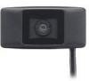
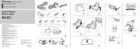
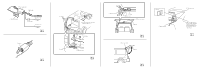
This device complies with Part 15 of the FCC Rules. Operation is subject to the following two conditions: (1) This device may not cause harmful interference, and (2) this device must accept any interference received, including interference that may cause undesired operation. Information to User Alteration or modifications carried out without appropriate authorization may invalidate the user's right to operate the equipment. WARNING: Handling the cord on this product or cords associated with accessories sold with the product will expose you to lead, a chemical known to the State of California and other governmental entities to cause cancer and birth defects or other reproductive harm. Wash hands after handling. IMPORTANT SAFEGUARDS • Installation and wiring of this product require specialist skill and experience. To assure your safety, please request a specialist technician to install the unit. • This product is a rear view camera for checking the view at the rear of a car. A rear view camera is a camera that provides symmetrical images in the same way as rear and side view mirrors. • Connection to a TV with an RCA video input is possible, but confirm whether the TV you use has a reverse gear connection function. • Direct sunlight or strong light (sunlight reflected from a bumper etc) on the camera may result in smear above and below the location where the light strikes, but this is not a malfunction. • This product is designed to supplement the driver's rear view, but the camera images do not show all dangers and obstacles. Be sure to look behind you when reversing to confirm the view. • This product features a wide-angle lens, so the near view is wide and the far view is narrow, which may create a false sense of distance. Be sure to look behind you when reversing to confirm the view. • Do not wash your car with an automatic car wash or high-pressure water as it may result in water entering the camera or the camera falling off. • Check camera stand installation before driving. Are the screws loose? - Is the camera stand firmly secured? - If the rear view camera comes loose while you are driving it may cause an accident. Installation Parts supplied A Rear view camera × 1 B Power supply unit × 1 C RCA cable × 1 D Rear view camera stand × 1 E Hexagon wrench × 1 F Velcro tape (soft type) × 1 G Velcro tape (hard type) × 1 H Installation screws (3 × 4 mm) × 2 I Waterproof pad × 1 J Clamp × 10 K Double-sided tape × 1 L Lock tie × 1 Installation example (Fig. 1) 1 Glass surface 2 Make sure it doesn't touch the wiper 3 Install on the center part Changing the orientation of camera stand installation (Fig. 2) Changing the orientation of camera stand installation bracket A enables a variety of installation possibilities. Change to match your car's shape or the installation site. • Use the hexagon wrench to remove the screws securing camera stand brackets A and B. • Change the orientation of installation bracket A, and then secure with the screws again. Note: • Before finally installing the unit, connect the wiring temporarily, making sure it is all connected up properly, and the unit and the system work properly. • Use only the parts included with the unit to ensure proper installation. The use of unauthorized parts can cause malfunctions. • Consult with your nearest dealer if installation requires the drilling of holes or other modifications of the vehicle. • Install the unit where it does not get in the driver's way and cannot injure the passenger if there is a sudden stop, like an emergency stop. • When mounting this unit, make sure none of the leads are trapped between this unit and the surrounding metalwork or fittings. • Do not mount this unit near the heater outlet, where it would be affected by heat, or near the doors, where rainwater might splash onto it. (Never install in locations such as the above because of the danger of malfunction due to high temperatures.) • Before drilling any mounting holes always check behind where you want to drill the holes. Do not drill into the gas line, brake line, electrical wiring or other important parts. • If this unit is installed in the passenger compartment, anchor it securely so it does not break free while the car is moving, and cause injury or an accident. • If this unit is installed under a front seat, make sure it does not obstruct seat movement. Route all leads and cords carefully around the sliding mechanism so they do not get caught or pinched in the mechanism and cause a short circuit. • Locate in the position you want to install the rear view camera. Adjust the angle of the rear view camera, and install so that the camera doesn't touch the car. • When sticking to a glass surface, stick it on in a position that assures the camera doesn't touch the rear window. • Install so that it does not obstruct the rear field of view. • Install so that it does not protrude from the side of the car. • Do not perform installation in rain or fog. • When humidity is high, dry the surface to which the unit is to be attached before installing. Moisture on the attachment surface reduces adhesive strength which may lead to the unit coming off. • If the temperature of the attachment surface is low, warm with a hair dryer of other means before installing to improve adhesive strength. • Do not attach the camera stand to areas on the car body treated with fluorocarbon resin, or glass. This may result in the rear view camera falling off. • During the 24-hour period after installing: - Do not apply water to the unit. - Do not expose the unit to rain. - Do not subject the camera to unnecessary force. • Thoroughly clean where tape is used for sticking on the unit. 1. Clean the surface to which the rear view camera is to be installed. (Fig. 3) Use a cloth or other item to wipe oil, wax, dust and any other dirt from the installation surface. 2. Align the camera stand with the installation surface. (Fig. 4) Adjust the camera stand so that there is no space between it and the installation surface. 1 Turn 2 Twist 3 Camera stand 3. Attach the rear view camera to the camera stand with the installation screws. (Fig. 6) Depending on the side you want the cable to come out of, pass it through the groove. 1 Top 2 Rear view camera 3 Bottom 4 Installation screw 5 Camera stand 4. Peel off the sheet on the back of they camera stand and stick it on. (Fig. 5, Fig. 7) Press the camera stand with your fingers to stick it to the installation surface. Touching the adhesive surface or sticking the unit on a second time reduces adhesive power which may result in the unit coming off. 1 Camera stand 2 Stick in the center 5. Adjust the angle so that the bumper or rear edge of the car is displayed at the bottom of the TV screen. (Fig. 8, Fig. 9, Fig. 10) 1 Angle of view Horizontal: 112° 2 Angle of view Vertical: 82° 3 Bumper or rear edge of car 6. Install the power supply unit. (Fig. 11) Stick Velcro tape (hard type) to the bottom of the power supply unit, and stick Velcro tape (soft type) to the installation site. • You can use Velcro tape (hard type) to attach directly to a carpet, but do not use the soft type. • Install the power supply unit close enough for the rear view camera cable to reach. PRECAUCIONES DE SEGURIDAD IMPORTANTES • La instalación y cableado de este producto requiere la habilidad y experiencia de un especialista. Para asegurar la seguridad, solicite un técnico especialista para instalar la unidad. • Este producto es una cámara de vista posterior para verificar la vista en la parte trasera de un coche. Una cámara de vista posterior es una cámara que provee imágenes simétricas de la misma manera que los espejos retrovisores o laterales. • Se puede hacer la conexión a un televisor con entrada de vídeo RCA, pero compruebe si el televisor tiene una función de conexión de marcha atrás. • La luz directa del sol o luz fuerte (luz del sol reflejada de un parachoques, etc.) en la cámara puede producir una mancha por encima y por debajo de la ubicación donde la luz radia, pero esto no es un fallo de funcionamiento. • Este producto ha sido diseñado para complementar la vista trasera del conductor, pero las imágenes de la cámara no muestran todos los peligros y obstáculos. Asegúrese de mirar atrás cuando vaya de marcha atrás para comprobar la vista. • Este producto tiene una lente de gran angular y, por lo tanto, la vista cercana es amplia y la vista distante es estrecha, lo que puede crear una sensación falsa de la distancia. Asegúrese de mirar atrás cuando vaya de marcha atrás para comprobar la vista. • No lave su coche en un túnel de lavado automático o agua de alta presión, ya que esto puede resultar en la entrada de agua en la cámara o caída de la cámara. • Verifique la instalación del soporte de la cámara antes de conducir el coche. ¿No están flojos los tornillos? - ¿Está firmemente fijo el soporte de la cámara? - Si la cámara de vista posterior se afloja mientras está conduciendo, esto puede causar un accidente. Instalación Piezas suministradas A Cámara de vista posterior × 1 B Unidad de suministro de energía × 1 C Cable RCA × 1 D Soporte de la cámara de vista posterior × 1 E Llave hexagonal × 1 F Cinta velcro (tipo blanda) × 1 G Cinta velcro (tipo dura) × 1 H Tornillos de instalación (3 × 4 mm) × 2 I Almohadilla impermeable × 1 J Abrazadera × 10 K Cinta de doble cara × 1 L Enlace de fijación × 1 Ejemplo de instalación (Fig. 1) 1 Superficie de vidrio 2 Asegúrese de que no toque el limpiador 3 Instale en la pieza central Cambio de la orientación de la instalación del soporte de la cámara (Fig. 2) Cambiar la orientación de la ménsula A de la instalación del soporte de la cámara permite una gran variedad de posibilidades de instalación. Cambie de acuerdo con a la forma de su coche o sitio de instalación. • Utilice la llave hexagonal para sacar los tornil- los que fijan las ménsulas A y B del soporte de la cámara. • Cambie la orientación de la ménsula A de instalación y, a continuación, fíjela nuevamente con los tornillos. Nota: • Antes de finalizar la instalación de la unidad, conecte el cableado temporariamente, asegurándose de que todo se encuentra conectado apropiadamente, y la unidad y el sistema funcionan apropiadamente. • Utilice solamente las partes incluídas con la unidad para asegurar una instalación adecuada. El uso de partes no autorizadas puede ocasionar fallas de funcionamiento. • Si la instalación requiere del taladrado de orificios u otras modificaciones del vehículo, consulte con su agente o concesionario más cercano a su domicilio. • Instale la unidad en donde no interfiera con el conductor y no pueda lesionar al pasajero en caso de una parada repentina, tal como una frenada de emergencia. • Cuando monte esta unidad, cerciórese que ninguno de los cables queda aprisionado entre esta unidad y accesorios o partes metálicas circundantes. • No monte esta unidad cerca de la salida del calefactor, en donde podría ser afectado por el calor o cerca de las puertas, en donde la lluvia podría salpicar sobre la misma. (Para evitar el riego de fallos de funcionamiento producidos por las altas temperaturas, evite la instalación en los lugares arriba.) • Antes de taladrar cualquier orificio de montaje siempre compruebe lo que hay detrás en donde desea taladrar los orificios. No taladre en la línea de combustible, cableado eléctrico u otras partes importantes. • Si esta unidad es instalada en el compartimiento de pasajeros, fíjela seguramente de modo que no se desprenda mientras el automóvil se encuentra en movimiento, y pueda ocasionar lesiones o accidentes. • Si esta unidad se instale bajo un asiento delantero, cerciórese de que no obstruye el movimiento del asiento. Pase todos los cables y conductores cuidadosamente a través de los mecanismo deslizantes, de modo que no queden aprisionados o atrapados en el mecanismo y ocasionen un corto circuito. • Encuentre la posición que desea instalar la cámara de vista posterior. Ajuste el ángulo de la cámara de vista posterior, e instale de modo que la cámara no toque el coche. • Cuando fije a una superficie de vídeo, fíjela en una posición que asegure que la cámara no toque la ventana trasera. • Instale de modo que no obstruya el campo de vista trasero. • Instale de modo que no se sobresalga del lado del coche. • No realice la instalación en la lluvia o niebla. • Cuando la humedad está alta, seque la superficie a la cual fijará la unidad antes de instalar. La humedad de la superficie de fijación reduce la resistencia de adherencia, lo que puede soltar la unidad. • Si la temperatura de la superficie de fijación está baja, caliente con un secador de pelo u otro medio antes de instalar, para mejorar la resistencia de adherencia. • No fije el soporte de la cámara en áreas en la carrocería del coche tratadas con resina de fluorocarburo, o vidrio. Esto puede resultar en la caída de la cámara de vista posterior. • Durante el período de 24 horas tras la instalación: - No aplique agua a la unidad. - No exponga la unidad a la lluvia. - No sujete la cámara a la fuerza innecesaria. • Limpie completamente el sitio donde se utilizará la cinta para fijar la unidad. 1. Limpie la superficie a la cual se instalará la cámara de vista posterior. (Fig. 3) Utilice un paño u otro ítem para limpiar el aceite, cera y cualquier otra suciedad de la superficie de instalación. 2. Alinee el soporte de la cámara con la superficie de instalación. (Fig. 4) Ajuste el soporte de la cámara de modo que no quede ningún espacio entre ello y la superficie de instalación. 1 Gire 2 Retuerza 3 Soporte de la cámara 3. Fije la cámara de vista posterior al soporte de la cámara con los tornillos de instalación. (Fig. 6) Dependiendo del lado que desea que el cable salga, páselo a través de la ranura. 1 Parte superior 2 Cámara de vista posterior 3 Parte inferior 4 Tornillo de instalación 5 Soporte de la cámara 4. Quite la hoja de la parte posterior del soporte de la cámara y fije. (Fig. 5, Fig. 7) Presione el soporte de la cámara con los dedos para fijarlo en la superficie de instalación. Tocar la superficie adhesiva o fijar la unidad una segunda vez reduce la resistencia de adherencia, lo que puede resultar en el despegamiento de la unidad. 1 Soporte de la cámara 2 Fije en el centro 5. Ajuste el ángulo de modo que el parachoques o borde trasero del coche se visualice en la parte inferior de la pantalla de TV. (Fig. 8, Fig. 9, Fig. 10) 1 Ángulo de visión Horizontal: 112° 2 Ángulo de visión Vertical: 82° 3 Parachoques o borde trasero del coche 6. Instale la unidad de suministro de energía. (Fig. 11) Fije la cinta velcro (tipo dura) en la parte inferior de la unidad de suministro de energía, y fije la cinta velcro (tipo blanda) en el sitio de instalación. • Puede utilizar la cinta velcro (tipo dura) para fijar directamente a una alfombra, pero no utilice el tipo de cinta blanda. • Instale la unidad de suministro de energía lo suficiente cercano para que el cable de la cámara de vista posterior la alcance.
-
 1
1 -
 2
2 -
 3
3 -
 4
4 -
 5
5 -
 6
6 -
 7
7 -
 8
8
 |
 |
