Pioneer ND-BC1 Other Manual - Page 6
Especificaciones, <ESPAÑOL>, Conexión, Specifications, <ENGLISH>, Connection
 |
UPC - 012562706498
View all Pioneer ND-BC1 manuals
Add to My Manuals
Save this manual to your list of manuals |
Page 6 highlights
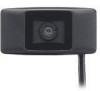
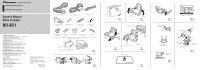
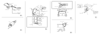
OF OF OF OF N STAR N STAR N STAR N STAR Connection Note: • This unit is for vehicles with a 12-volt battery and negative grounding. Before installing it in a recreational vehicle, truck, or bus, check the battery voltage. • To avoid shorts in the electrical system, be sure to disconnect the ≠ battery cable before beginning installation. • Refer to the owner's manual for details on connecting the other units, then make connections correctly. • Secure the wiring with cable clamps or adhesive tape. To protect the wiring, wrap adhesive tape around them where they lie against metal parts. • Route and secure all wiring so it cannot touch any moving parts, such as the gear shift, handbrake and seat rails. Do not route wiring in places that get hot, such as near the heater outlet. If the insulation of the wiring melts or gets torn, there is a danger of the wiring short-circuiting to the vehicle body. • Do not shorten any leads. • Never feed power to other equipment by cutting the insu- lation of the power supply lead of the unit and tapping into the lead. The current capacity of the lead will be exceeded, causing over heating. • When replacing fuse, be sure to use only fuse of the rating prescribed on the fuse holder. • To minimize noise locate the TV antenna cable, radio antenna cable and RCA cable as far away from each other as possible. • Connection to a TV with an RCA video input is possible, but confirm whether the TV you use has a reverse gear connection function. • If this unit is installed in a vehicle that does not have an ACC (accessory) position on the ignition switch, the red lead of the unit should be connected to a terminal coupled with ignition switch ON/OFF operations. If this is not done, the vehicle battery may be drained when you are away from the vehicle for several hours. F ACC O F O T T ACC position No ACC position • Cords for this product and those for other products may be different colors even if they have the same function. When connecting this product to another product, refer to the supplied manuals of both products and connect cords that have the same function. Connection sample (Fig. 12) 1 Power supply unit 2 Rear view camera Video input jack Connect to video input jack. 3 RCA cable Accessory power supply To electric terminal controlled by ignition switch (12 V DC) ON/OFF. 4 Red 5 Fuse (1A) Ground To vehicle (metal) body. 6 Black Installation with a lock tie (Fig. 13) When connecting the rear view camera and the power supply unit, secure the cord to the power supply unit with the lock tie. 1 Lock tie Cord installation (Fig. 14) 1 Clamps 2 Rear view camera 3 RCA cable 4 Product with a video input jack (Hideaway unit etc.) 5 Power supply unit 6 Made with a rasp etc. 7 Scuff plate 8 Clamp 9 Waterproof plate Cord installation points (Fig. 15) • When pulling the cord out of the car, pull from the outer side of the hatch harness cover and hinge. 1 Pull out from here 2 Hinge 3 Harness cover 4 Rear view camera 5 Hatch After cord installation (Fig. 16, Fig. 17) • Open and close the hatch door slowly to confirm that the cord is not rubbing against the rim of the door. 1 Rear view camera 2 Hatch 3 Cord • When the rear view camera cord cannot be pulled out from the lower side due to the type of car. As shown in the figure 17, bend the cord into a U shape in front of the waterproof pad, making sure that rain water cannot enter the car by running down the cord. 1 Clamps 2 Waterproof pad 3 Rubber packing 4 Make a U-shaped loop in the lead outside the rubber packing to prevent rainwater from flowing along the lead into the interior of the vehicle. Specifications Power source 14.4 V DC (10.8 - 15.1 V allowable) Grounding system Negative type Max. current consumption 130 mA Output video Mirror image (for rear view confirmation) Sensor 1/4-inch color CCD sensor No. of pixels ........ 491 (vertical) × 512 (horizontal) (Effective no. of pixels roughly 250,000) Lens Wide-angle, focal length f = 1.94 mm, F value 2.8 Angle of view Horizontal: approx. 112º Vertical: approx. 82º Iris system Electronic iris Scanning system Interlace Synchronizing system ........ Internal synchronization Signal-to-noise ratio 40 dB or more (at the recommended intensity of illumination) Horizontal resolution Approx. 300 TV lines Illumination range .......... Approx. 1.5 - 100,000 lux Image output 1 Vp-p (75 Ω) Operation temperature range 10ºC - +60ºC +14ºF - +140ºF Storage temperature range 20ºC - +80ºC -4ºF - +176ºF Dimensions Camera unit .... 50 (W) × 25 (H) × 20.5 (D) mm 2 (W) × 1 (H) × 3/4 (D) in. Power supply unit 70 (W) × 35 (H) × 25 (D) mm 2-3/4 (W) × 1-3/8 (H) × 1 (D) in. Weight Camera unit 120 g (0.3 lbs) (including the cable) Power supply 150 g (0.3 lbs) (including the power cord) Note: Specifications and the design are subject to possible modification without prior notice due to improvements. Conexión Nota: • Esta unidad es para vehículos con una batería de 12 voltios y masa negativa. Antes de montarlo en un autobús, camión o vehículo de recreación, compruebe el voltaje de la batería. • Para evitar cortocircuitos en el sistema eléctrico, cerciórese de desconectar el cable de batería ≠ antes de comenzar la instalación. • Para los detalles sobre la conexión a otras unidades, refiérase al manual del propietario y luego haga las conexiones correctamente. • Asegure el cableado con grapas de cable o cinta aisladora. Para proteger el cableado, envuelva con cinta aisladora alrededor del cableado en las partes en donde se apoya contra las partes metálicas. • Pase y asegure todo el cableado de modo que no toque ninguna de la partes móviles, tales como engranaje de cambio, freno de mano y carriles del asiento. No pase el cableado por lugares que se calientan, tales como cerca una salida del calefactor. Si la aislación del cableado se derrite o se rompe, existe el peligro de que el cableado se ponga en cortocircuito con la carrocería del vehículo. • No ponga en cortocircuito ninguno de los conductores. • No alimente otro equipo cortando la aislación del conductor de suministro de alimentación de la unidad y enrrollando en el conductor. La capacidad actual del conductor será excedida, ocasionando sobrecalentamiento. • Cuando reemplace el fusible, cerciórese de usar solamente el fusible indicado en el portafusible. • Para minimizar el ruido, ubique el cable de antena de TV, cable de antena de radio y cable RCA lo más lejos posible el uno del otro. • Se puede hacer la conexión a un televisor con entrada de vídeo RCA, pero compruebe si el televisor tiene una función de conexión de marcha atrás. • Si se instala esta unidad en un vehículo que no tiene una posición ACC (accesorio) en el interruptor de encendido, el conductor rojo de la unidad deberá conectarse al terminal conectado con las operaciones del interruptor de encendido ON/OFF. Si no se hace esto, la batería del vehículo podría drenarse cuando usted esté lejos del vehículo por varias horas. F ACC O F O T T Posición ACC No en la posición ACC • Los cables para este producto y aquéllas para otros productos pueden ser de colores diferentes aun si tienen la misma función. Cuando se conecta este producto a otro, refiérase a los manuales de ambos productos y conecte los cables que tienen la misma función. Muestra de conexión (Fig. 12) 1 Unidad de suministro de energía 2 Cámara de vista posterior Toma de entrada de vídeo Conecte a la toma de entrada de vídeo. 3 Cable RCA Suministro de energía de accesorios Al terminal de energía eléctrica controlado por el interruptor de encendido del vehículo (12 V CC) ON/OFF. 4 Rojo 5 Fusible (1A) Conexión a tierra A la carrocería del vehículo (parte metálica). 6 Negro Instalación con un enlace de fijación (Fig. 13) Cuando conecte la cámara de vista posterior y la unidad de suministro de energía, fije el cable a la unidad de suministro de energía con el enlace de fijación. 1 Enlace de fijación Instalación del cable (Fig. 14) 1 Abrazaderas 2 Cámara de vista posterior 3 Cable RCA 4 Producto con una toma de entrada de vídeo (Unidad oculta, etc.) 5 Unidad de suministro de energía 6 Hecho con una escofina, etc. 7 Placa de marca 8 Abrazadera 9 Placa impermeable Puntos de instalación del cable (Fig. 15) • Cuando tire del cable del coche, tire del lado exterior de la cubierta de arnés de la escotilla y de la bisagra. 1 Tire de aquí 2 Bisagra 3 Cubierta de arnés 4 Cámara de vista posterior 5 Escotilla Tras la instalación del cable (Fig. 16, Fig. 17) • Abra y cierre lentamente la puerta de escotilla para comprobar que el cable no está frotando contra borde de la puerta. 1 Cámara de vista posterior 2 Escotilla 3 Cable • Cuando no se puede tirar de la cámara de vista posterior desde el lado inferior debido al tipo de coche. Como se muestra en la figura 17, doble el cable en una forma de "U" delante de la almohadilla impermeable, asegurándose de que el agua de la lluvia no pueda entrar en el coche bajando corriendo por el cable. 1 Abrazaderas 2 Almohadilla impermeable 3 Empaquetadura de caucho 4 Haga lazo en forma de "U" en el cable fuera de la empaquetadura de caucho para evitar que el agua de la lluvia fluya a lo largo del cable al interior del vehículo. Especificaciones Fuente de alimentación CC 14,4 V 10,8 - 15,1 V permisible) Sistema de conexión a tierra Tipo negativo Consumo de corriente máx 130 mA Vídeo de salida Imagen de espejo (para confirmación de vista posterior) Sensor .......... Sensor CCD de color de 1/4 pulgadas No. de píxeles ...... 491 (vertical) × 512 (horizontal) (No. efectivo de píxeles aproximadamente 250.000) Lente Gran angular, distancia focal f = 1,94 mm, valor F 2.8 Ángulo de visión Horizontal: aprox. 112º Vertical: aprox. 82º Sistema de diafragma Diafragma electrónico Sistema de escaneo Entrelazado Sistema de sincronización .... Sincronización interna Relación señal/ruido 40 dB o superior (en la intensidad recomendad de iluminación) Resolución horizontal ...... Aprox. 300 líneas de TV Rango de iluminación Aprox. 1,5 - 100.000 lux Salida de imagen 1 Vp-p (75 Ω) Rango de temperatura de funcionamiento 10ºC - +60ºC Rango de temperatura de almacenamiento 20ºC - +80ºC Dimensiones Unidad de cámara 50 (An.) × 25 (Al.) × 20,5 (Pr.) mm Unidad de suministro de energía 70 (An.) × 35 (Al.) × 25 (Pr.) mm Peso Unidad de cámara 120 g (incluyendo el cable) Suministro de energía 150 g (incluyendo el cable) Nota: Las especificaciones y el diseño están sujetos a posibles modificaciones sin previo aviso debido a mejoramientos.
-
 1
1 -
 2
2 -
 3
3 -
 4
4 -
 5
5 -
 6
6 -
 7
7 -
 8
8
 |
 |
