Pioneer SC-68 Owner's Manual - Page 32
Important
 |
View all Pioneer SC-68 manuals
Add to My Manuals
Save this manual to your list of manuals |
Page 32 highlights
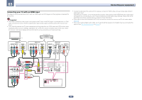
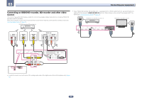
03 Connecting your equipment Connecting your TV with no HDMI input This diagram shows connections of a TV (with no HDMI input) and DVD player (or other playback component) to the receiver. Important ! With these connections, the picture is not output to the TV even if the DVD player is connected with an HDMI cable. Connect the receiver and TV using the same type of video cable as used to connect the receiver and player. ! Also, when the receiver and TV are connected by anything other than an HDMI cable, the OSD function allowing display of the receiver's settings, operations, etc., on the TV's screen cannot be used. In this case, watch the receiver's front panel display while performing the various operations and making settings. ! In order to listening to HD audio with this receiver, connect an HDMI cable, and use analog video cable for video signal input. Depending on the player, it may not be possible to output video signals to both HDMI and other video output (composite, etc.) simultaneously, and it may be necessary to make video output settings. Please refer to the operating instructions supplied with your player for more information. ! If you want to listen to the sound of the TV over the receiver, connect the receiver and TV with audio cables (page 30). ! If you use an optical digital audio cable, you'll need to tell the receiver which digital input you connected the player to (see The Input Setup menu on page 47). DVD player, etc. TV Select one COMPONENT VIDEO IN Y PB PR VIDEO IN VIDEO Select one COMPONENT VIDEO OUT Y PB PR VIDEO OUT VIDEO HDMI OUT Select one DIGITAL OUT COAXIAL OPTICAL AUDIO OUT R ANALOG L IN 1 (DVD) ASSIGNABLE COMPONENT VIDEO Y PB PR IN 1 (DVD) IN 2 (DVR/ BDR) IN 3 (VIDEO) MONITOR OUT BD IN DVD IN IN 2 IN 3 IN 4 IN 6 (SAT/CBL) (DVR/BDR) (VIDEO) MONITOR OUT IN 7 OUT 2 OUT 1 LAN(10/100) DC OUTPUT for WIRELESS LAN (CONTROL) (OUTPUT 5 V 0.6 A MAX) COAXIAL ASSIGNABLE OPTICAL ASSIGNABLE IN 1 IN 2 IN 1 IN 2 OUT (DVD) (SAT/CBL) (TV) (DVR/BDR) IN 1 (DVD) ASSIGNABLE COMPONENT VIDEO Y PB PR IN 1 (DVD) IN 2 (DVR/ BDR) IN 3 (VIDEO) MONITOR OUT BD IN DVD IN IN 2 IN 3 IN 4 IN 6 (SAT/CBL) (DVR/BDR) (VIDEO) MONITOR OUT IN 7 OUT 2 OUT 1 LAN(10/100) DC OUTPUT for WIRELESS LAN (CONTROL) (OUTPUT 5 V 0.6 A MAX) COAXIAL ASSIGNABLE OPTICAL ASSIGNABLE IN 1 IN 2 IN 1 IN 2 OUT (DVD) (SAT/CBL) (TV) (DVR/BDR) 32
-
 1
1 -
2
-
3
-
4
-
5
-
6
-
7
-
8
-
9
-
10
-
11
-
12
-
13
-
14
-
15
-
16
-
17
-
18
-
19
-
20
-
21
-
22
-
23
-
24
-
25
-
26
-
 27
27 -
 28
28 -
 29
29 -
 30
30 -
 31
31 -
 32
32 -
 33
33 -
 34
34 -
 35
35 -
 36
36 -
 37
37 -
38
-
39
-
40
-
41
-
42
-
43
-
44
-
45
-
46
-
47
-
48
-
49
-
50
-
51
-
52
-
53
-
54
-
55
-
56
-
57
-
58
-
59
-
60
-
61
-
62
-
63
-
64
-
65
-
66
-
67
-
68
-
69
-
70
-
71
-
72
-
73
-
74
-
75
-
76
-
77
-
78
-
79
-
80
-
81
-
82
-
83
-
84
-
85
-
86
-
87
-
88
-
89
-
90
-
91
-
92
-
93
-
94
-
95
-
96
-
97
-
98
-
99
-
100
-
101
-
102
-
103
-
104
-
105
-
106
-
107
-
108
-
109
-
110
-
111
-
112
-
113
-
114
-
115
-
116
-
117
-
118
-
119
-
120
-
121
-
122
-
123
-
124
-
125
-
126
-
127
-
128
-
129
-
130
-
131
 |
 |
