Pioneer SX-255R Service Manual - Page 13
Isch I5
 |
View all Pioneer SX-255R manuals
Add to My Manuals
Save this manual to your list of manuals |
Page 13 highlights
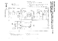
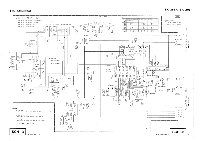
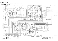
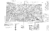
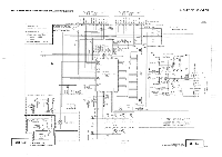
SX-255R, SX-205 5.3 VOL. ASSY, FL AND UCOM ASSY AND POWER SW. ASSY (for SX-255R) • VOL. Assy VOLUME MOTOR DRIVE +5.3V,„ . %12 2SA1115-E/F ma 0613 2SA1115- F 1 CN3I KPE12I L IN 0 TONE L A GNO 0 R IN 0 O OUT O- A (IND O our 0- 7V +12V 0 5.BASS IC601(/2) N45580-0 3 4 ovr 2 8 R625 100 C605 2.2/50 o VOLUME 1363 0.015 R631 R633 75K 75K C633 = 0.082 5.BASS ON/OFF Q631 DTC14355-T Q632 DTC14365-7 C606 5 2.2/50 C634 = ? ,( 082 75K 75K C632 • 0.015 -7_ 6 R626 5 100 10601 (2/2) NJIM45580-0 +12.2V OV C609 4.7/50 CG1 0 4.7/50 VOL. ASSY (AWZ8092 SX-255R/KUXJ, KCXJ, YPWXJ) (AWZ8093 SX-205/KUXJ, SDXJ) ** V8601 SX-255R/KUXJ, KCXJ, YPWXJ SX-205/KUXJ, SDXJ ACX7021 ACT7001 Noted , 1 .Resistores Indicated In ohm. 1"W. tolerance IS% unless otherwise noted Mt k ohm. M:AA ohm 2.Capacitors Indicated in C.O.. ty (uF) Vol tags(V) unless otherwise noted o,oF r'Idi oatl on wi thout vol tape Is GOY M CCMA NP,CEANP TY:OFTXA SIGNAL ROUTE 010,, AUD10 SIGNAL ROUTE SCH 5 18 VOL. ASSY POWER SW. Assy (for SX-255R) RWZ8094 0 0875 O STANDBY ,,975 IND C"^x", POWER 5871 as STANDBY IND 0. END K13 KO2 • This diagram is viewed from the mounted parts side. The parts mounted on this PCB include all necessary parts for several destinations. For further information for respective destinations, be sure to check with the schematic diagram. To MOTHER ASSY CN4 ,- To MOTHER ASSY CN5 FL AND UCOM Assy 0 OR OILY H41 O 054 X'J 0,, CO C855 (O O 0) p8 O- ON 001.5i0 E 06t .30 (g, a (,) 0 W 1 fi_ .2'152571' CINL ) 0 4252 0 000 0 o 15 W 0 0842 0 02, 0-4 LS83 8488 04'
-
 1
1 -
2
-
3
-
4
-
5
-
6
-
7
-
 8
8 -
 9
9 -
 10
10 -
 11
11 -
 12
12 -
 13
13 -
 14
14 -
 15
15 -
 16
16 -
 17
17 -
 18
18 -
19
-
20
-
21
-
22
-
23
-
24
-
25
-
26
-
27
-
28
-
29
 |
 |
