Pioneer SX-255R Service Manual - Page 7
SX-255R, SX-205
 |
View all Pioneer SX-255R manuals
Add to My Manuals
Save this manual to your list of manuals |
Page 7 highlights
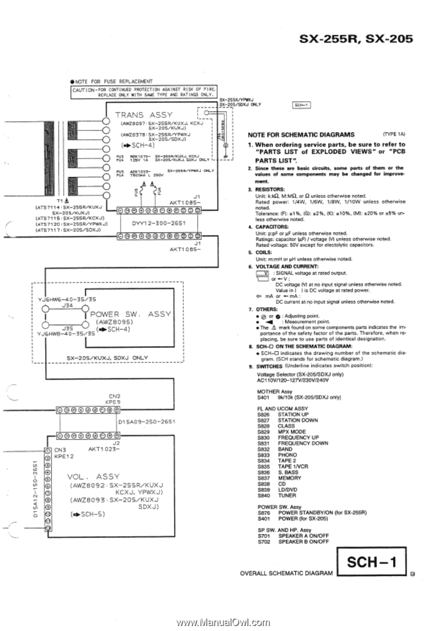
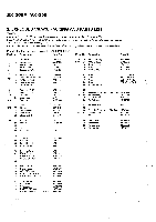
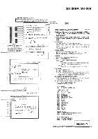
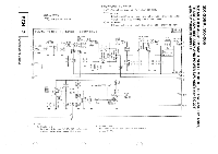
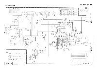
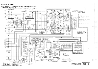
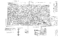
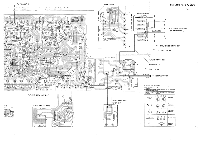
SX-255R, SX-205 *N0TE FOR FUSE REPLACEMENT CAUTION -FOR CONTINUED PROTECTION AGAINST RISK OF FIRE, REPLACE ONLY WITH SAME TYPE AND RATINGS ONLY. SX-25SIR/YPWXJ SX-20S/SOXJ ONLY SCH-1 TRANS ASSY 1--- 1 (AWZ8097 SX-2S5R/KUXJ.KGXJ SX-205/KUXJ) (AWZ8378 SX-255R/YPWXJ SX-205/SDXJ) (igi.SCH-4) FU3 FU4 REK1075- SX-255R/KUXJ, KCXJ 125V 1A SX-205/XUXJ, SDXJ ONLY FU3 AEK1053- SX-255R/YPWXJ ONLY FU4 TSOOmA L 250V T1 (ATS7114 :SX-255R/KUXJ SX-205/KUXJ) (ATS7115:SX-255R/KCXJ) (ATS7120 , SX-255R/YPWXJ) (ATS7117.SX-205/SIDXJ) J1 AKT1 08S- N N • DYY1 2-3 0 0-2 6 61 N K, N • J1 AKT1 0 85- YJGHWG-40-35 /3S 0 J34 POWER SW. (AWZ8095) J3S (04Ilo.SCH-4) YJEHW8-40-36 /35 ASSY SX-2 OS/KUXJ, SDXJ ONLY NOTE FOR SCHEMATIC DIAGRAMS (TYPE 1A) 1. When ordering service parts, be sure to refer to "PARTS UST of EXPLODED VIEWS" or "PCB PARTS LIST". 2. Since these are basic circuits, some parts of them or the values of some components may be changed for improve- ment. 3. RESISTORS: Unit: k:kO, M:MQ, or 0 unless otherwise noted. Rated power: 1/4W, 1/6W, 1/8W, 1/10W unless otherwise noted. Tolerance: (F): *1%, (G): t2%, (K): *10%, (M): *20% or ±5% un- less otherwise noted. 4. CAPACITORS: Unit: p:pF or µF unless otherwise noted. Ratings: capacitor (µF) / voltage (V) unless otherwise noted. Rated voltage: 50V except for electolytic capacitors. 5. COILS: Unit: m:mH or µH unless otherwise noted. 6. VOLTAGE AND CURRENT: V : SIGNAL voltage at rated output. ono-V: DC voltage (V) at no input signal unless otherwise noted. Value in ( is DC voltage at rated power. 4= mA or A-- mA : DC current at no input signal unless otherwise noted. 7. OTHERS: • a or p : Adjusting point. • -.4 : Measurement point. •The mark found on some components parts indicates the importance of the safety factor of the parts. Therefore, when replacing, be sure to use parts of identical designation. 8. SCH-O ON THE SCHEMATIC DIAGRAM: • SCHAD indicates the drawing number of the schematic diagram. (SCH stands for schematic diagram.) 9. SWITCHES (Underline indicates switch position): Voltage Selector (SX-205/SDXJ only) AC110V/120-127V/230V/240V N CN3 2 KPE1 2 N 0 CN2 KPE9 • D1 SA09-200-2 651 • J2 AKT1 0 2 3- 4 VOL. ASSY 6 (AVVZ8092 SX-255R/KUXJ 7 KCXJ, YPWXJ) (AWZ8093:SX-205/KUXJ 9 SDXJ) (I40.SCH-B) MOTHER Assy S401 9k/10k (SX-205/SDXJ only) FL AND UCOM ASSY S826 STATION UP S827 STATION DOWN S828 CLASS S829 MPX MODE S830 FREQUENCY UP S831 FREQUENCY DOWN S832 BAND S833 PHONO S834 TAPE 2 S835 TAPE 1NCR S836 S. BASS S837 MEMORY S838 CD S839 LD/DVD S840 TUNER POWER SW. Assy S876 POWER STANDBY/ON (for SX-255R) S401 POWER (for SX-205) SP SW. AND HP. Assy S701 SPEAKER A ON/OFF S702 SPEAKER B ON/OFF OVERALL SCHEMATIC DIAGRAM SCH -1 9 D1SA1 2-150-2651
-
 1
1 -
 2
2 -
 3
3 -
 4
4 -
 5
5 -
 6
6 -
 7
7 -
 8
8 -
 9
9 -
 10
10 -
 11
11 -
 12
12 -
13
-
14
-
15
-
16
-
17
-
18
-
19
-
20
-
21
-
22
-
23
-
24
-
25
-
26
-
27
-
28
-
29
 |
 |