Pioneer VSX-49TXi Owner's Manual - Page 80
Multi-Room
 |
View all Pioneer VSX-49TXi manuals
Add to My Manuals
Save this manual to your list of manuals |
Page 80 highlights
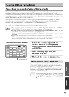
Using Other Functions Multi-Room When used together with an optional IR receiver, this receiver is capable of outputting two different sources at the same time. One to the VIDEO OUT jack and SPEAKERS terminals and another to the MULTI ROOM & SOURCE AUDIO and VIDEO OUT jacks. Thus the VSX-49TXi can power two independent systems, in separate rooms, listening to or watching different sources. With this system the two rooms can have completely independent power (the main room power can be off while the sub room is on) and the sub room can be controlled by this unit's remote control. If you go into the main room to change the source but forget the remote control it's not a problem. While in MULTI ROOM mode the input selector on the front panel of the VSX-49TXi is able to change the input even though the receiver is off. MULTI-ROOM connections On the VSX-49TXi, connect the IR receiver sensor to the MULTI-ROOM & SOURCE REMOTE IN jack, then connect a separate amplifier (and speakers) and TV monitor to the MULTI-ROOM & SOURCE AUDIO and VIDEO OUT jacks. All of this equipment should be placed in your sub-room as shown below. memo • When connecting the IR receiver, be sure to connect it to the green MULTI-ROOM & SOURCE REMOTE IN jack, not the black CONTROL IN or OUT jacks. • It is not possible to input digital signals into the sub room. If you wish to share output from a digital device to the sub room, you must also connect the digital device's source analog output into the receiver's input terminals. • You can't use tone controls (etc.) and any surround modes in the sub room. • If your i.LINK-equipped component cannot output both i.LINK and analog signals at the same time, and an i.LINK signal is selected in the main room, although it can be selected in the sub room, no sound is produced. Also, if a source component is selected for input in the sub room and the same component is then selected in the main room as an i.LINK source, the sound in the sub room stops. Sub room Main room DIGITAL PCM/2DIGITAL /DTS 2 OUT S400 (AUDIO) OUT 1 PHONO R AUDIO L OUT IN 7 (CD-R/ CD TAPE1 IN /MD) IN 6 (VCR2) IN R 5 OUT (VCR1 REC IN /DVR) CD-R/ TAPE1 4 /MD (SAT) IN IN PLAY 3 IN OUT (CD) REC TAPE2 MONITOR 2 IN (TV) IN PLAY 1 IN (DVD /LD) 2RF IN (DVD /LD) (For LD) ASSIGNABLE FRONT R SURROUND R AUDIO POWER AMP R L IN FRONT L R L CENTER 1 (Single) R R SUB W. L LR MULTI CH INPUT SUB W. PRE OUT 2 SURROUND L SURROUND BACK L (Single) CENTER SURROUND BACK L (Single) CONTROL IN MULTIROOM & SOURCE DVD /LD IN TV IN SAT IN OUT VCR1 /DVR IN OUT VCR2 IN MONITOR OUT OUT IN IN IN OUT IN OUT IN DVD /LD IN 1 Y PB PR IN 2 Y REMOTE IN MULTIROOM & SOURCE Y MONITOR OUT PB PR IN 3 Y PB PB PR PR COMPONENT VIDEO ASSIGNABLE R L AUDIO OUT OUT VCR3 IN IN VIDEO S2 VIDEO RS-232C ·Å ª ANTENNA L AM LOOP ANTENNA FM 75Ω UNBAL FRONT R CENTER L SURROUND R L SURROUND BACK R (Single) SPEAKERS AC OUTLET AC IN SPEAKERS ªı · L R Setup example Sub room (MR-100, amplifier, speakers and TV monitor) IR receiver (MR-100) Main room (Receiver, source components, front, center, and surround speakers, TV monitor etc.) 80
-
 1
1 -
2
-
3
-
4
-
5
-
6
-
7
-
8
-
9
-
10
-
11
-
12
-
13
-
14
-
15
-
16
-
17
-
18
-
19
-
20
-
21
-
22
-
23
-
24
-
25
-
26
-
27
-
28
-
29
-
30
-
31
-
32
-
33
-
34
-
35
-
36
-
37
-
38
-
39
-
40
-
41
-
42
-
43
-
44
-
45
-
46
-
47
-
48
-
49
-
50
-
51
-
52
-
53
-
54
-
55
-
56
-
57
-
58
-
59
-
60
-
61
-
62
-
63
-
64
-
65
-
66
-
67
-
68
-
69
-
70
-
71
-
72
-
73
-
74
-
 75
75 -
 76
76 -
 77
77 -
 78
78 -
 79
79 -
 80
80 -
 81
81 -
 82
82 -
 83
83 -
 84
84 -
 85
85 -
86
-
87
-
88
-
89
-
90
-
91
-
92
-
93
-
94
-
95
-
96
-
97
-
98
-
99
-
100
-
101
-
102
-
103
-
104
-
105
-
106
-
107
-
108
-
109
-
110
-
111
-
112
-
113
-
114
-
115
-
116
-
117
-
118
-
119
-
120
 |
 |
