Polk Audio PA D1000.1 PA D1000.1 Owner's Manual - Page 4
Amplifier Wiring, Amplifier Installation
 |
View all Polk Audio PA D1000.1 manuals
Add to My Manuals
Save this manual to your list of manuals |
Page 4 highlights
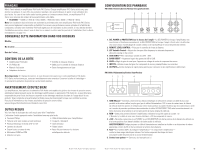
PA D1000.1 Power Inputs/Speaker Outputs 1 23 4 5 1000.1 Speaker Wiring Diagram PA D1000.1 The Polk Audio PA D1000.1 amplifier offers two positive and two negative output terminals for ease of connecting the speakers to the amplifier. Since this is a mono amplifier, connections are wired in paralleled internally. The amplifier is stable to 1 Ohm. 1. GND (Ground)-Connect this terminal directly to the metal chassis of the vehicle, using the shortest wire necessary to make this connection. Always use wire of the same gauge or larger than the +12V power wire. The chassis connection point should be scraped free of paint and dirt. Use only quality crimped and/or soldered connectors at both ends of this wire. DO NOT connect this terminal directly to the vehicle battery ground terminal or any other factory ground points. 2. REM (Remote Turn On)-This terminal turns on the amplifier when +12V is applied to it. Connect it to the remote turn on lead of the head unit. 3. +12V Power-Connect this terminal through a FUSE or CIRCUIT BREAKER to the positive terminal of the vehicle battery or the positive terminal of an isolated audio system battery. WARNING: Always protect this power wire by installing a fuse or circuit breaker of the appropriate size within 12" of the battery terminal connection. 4. Fuse-These fuses (40A x 3) protect the amplifier against internal electrical damage and are meant to protect only the amplifier. All other power connections should be fused at the power source. 5. Speaker Output-Connect your subwoofers here. 6. Terminal Adaptor-The adaptor enables the use of cable up to 0000AWG for the ground and +12V connections (see illustration below). 6. Terminal Adaptor Amplifier Wiring Power Connections • PA D1000.1 Fuse Size: 3 x 40 AMP ATC. • Power connections accept up to 4 AWG wire. • 4 AWG power and ground wire recommended for optimal performance. • Connect +12V to the battery through fuse holder. This connection provides +12V main power to the amplifier. • Power wire must be fused within 12" of the battery. • Ground the amplifier using a good chassis ground as close as possible to the amplifier. • Connect REM terminal to remote turn-on lead from the head unit. This connection provides +12V power to turn-on the amplifier. • Add extra ground wire between the negative terminal of the battery and the chassis. 1Ω min 2Ω min 2Ω min 2000.2 Amplifier Installation Mounting Locations The location of your amplifier will depend on several important issues. Due to the low profile and compact size of the Polk Audio PA D Series amplifier, there are many possible installation locations that will yield satisfactory amplifier performance. Always mount the amplifier in a place that protects the amplifier from the elements. In addition, mount the amplifier on a stable, flat surface. NOTE: MountingBRIaDGmED plifiers upside down is not recommendedBRIaDGnEDd may cause premature thermal shutdown. WARNING! Do not mount any amplifier in the engine compartment. Amplifiers are not designed GND to eRnEMdure t1h2Ve harsh environment of an engine compartment. L L R R 25A 25A L L R R Passenger Compartment If you are going to mount the amplifier in the passenger compartment, make sure you have adequate room for ventilation. When mounting your amplifier under a seat or similar area, keep a minimum of 1" of clearance around the amplifier for adequate cooling. Trunk Compartment Mount4inΩg ymoiunr amplifier in the trunk provides excelle2nΩt pmeirnformance as long as you do not restrict the airflow around the heatsink of the This type of mounting will amplifier. For yield the best optimal cooling dreuseulttos,thmeocuonntvtehcet2iaoΩmn pmelfififneiecrt with as much clearance as of the amplifier chassis. possible. 4000.4 RL RR FL FR RL RR FL FR REAR REAR FRONT FRONT GND GND REM REM 12V 12V 6 © 2011 Polk Audio-all rights reserved © 2011RLPolk ARRudio-FLall righFRts reserved 40A 40A 35A RL RR FL FR 7
-
 1
1 -
 2
2 -
 3
3 -
 4
4 -
 5
5 -
 6
6 -
 7
7 -
 8
8 -
 9
9 -
 10
10 -
11
-
12
-
13
-
14
-
15
-
16
-
17
-
18
-
19
-
20
-
21
-
22
-
23
-
24
-
25
-
26
-
27
-
28
-
29
-
30
-
31
-
32
 |
 |
