Poulan 1995-03 User Manual - Page 7
Assembly
 |
View all Poulan 1995-03 manuals
Add to My Manuals
Save this manual to your list of manuals |
Page 7 highlights
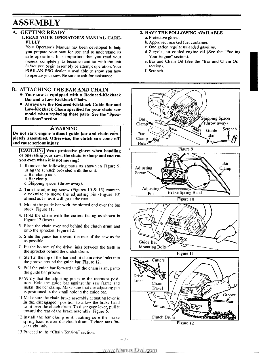
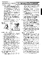
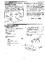
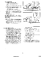
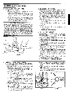
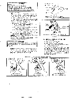
ASSEMBLY A. GETTING READY I. READ YOUR OPERATOR'S MANUAL CAREFULLY Your Operator's Manual has been developed to help you prepare your saw for use and to understand its safe operation. It is important that you read your manual completely to become familiar with the unit before you begin assembly or attempt operation. Your POULAN PRO dealer is available to show you how to operate your saw. Be sure to ask for assistance. 2. HAVE THE FOLLOWING AVAILABLE a. Protective gloves. b. Approved, marked fuel container c. One gallon regular unleaded gasoline. d.2 cycle, air-cooled engine oil (See the "Fueling Your Engine" section). C. Bar and Chain Oil (See the "Bar and Chain Oil" section). f. Scrench. B. ATTACHING THE BAR AND CHAIN • Your saw is equipped with a Reduced-Kickback Bar and a Low-Kickback Chain. • Always use the Reduced-Kickback Guide Bar and Low-Kickback Chain specified for your chain saw model when replacing these parts. See the "Specifications" section. A WARNING Do not start engine without guide bar and chain completely assembled. Otherwise, the clutch can come off and cause serious injury. CAUTION) Wear protective gloves when handling or operating your saw; the chain is sharp and can cu you even when it is not moving! 1. Remove the following parts as shown in Figure 9 using the scrench provided with the unit a Bar clamp nuts. h. Bar clamp. c. Shipping spacer (throw away). 2. Turn the adjusting screw (Figures 10 & 13) counterclockwise to move the adjusting pin (Figure 10) almost as far as it will go to the rear. 3. Mount the guide bar with the slotted end over the bar studs. Figure II. 4. Hold the chain with the cutters facing as shown in Figure 12 Onset). 5. Place the chain over and behind the clutch drum and onto the sprocket. Figure 12. 6. Slide the guide bar toward the rear of the saw as far as possible. 7. Fit the bottom of the drive links between the teeth in the sprocket behind the clutch dmm. 8. Start at the top of the bar and fit chain drive links into the groove around the guide bar. Figure 17. 9. Pull the guide bar forward until the chain is snug into the guide bar groove. 10.Verify that the adjusting pin is in the rearmost position. Hold the guide her against the saw frame and install the bar clamp. Make sure that the adjusting pin is positioned in the small hole in the guide bar. I I.Make sure the chain brake assembly actuating user is in the 'disengaged" position to allow the brake band to fit over the clutch drum. To disengage lever, pull it toward the rear of the brake assembly. Figure 5. 12.Install the bar clamp unit. making sure the brake spring hand is over the clutch drum. Tighten nuts finger tight only. 13.Procced to the "Chain Tension- section. B CIa Bar Clamp Nuts Adjusting Screw Shipping Spacer (throw away) Guide S" .ch Bar 3, Figure 9 Bar Clamp Adjusting Pin Brake Spring Band Figure I0 o Guide Bar Mounting Bolts Cutter \q. II Figure I I Links n. Chain Travel Clutch Drum Figure 12 Groove
-
 1
1 -
 2
2 -
 3
3 -
 4
4 -
 5
5 -
 6
6 -
 7
7 -
 8
8 -
 9
9 -
 10
10 -
 11
11 -
 12
12 -
13
-
14
-
15
-
16
-
17
-
18
-
19
-
20
-
21
 |
 |