Poulan 1999-12 User Manual - Page 5
Assembly
 |
View all Poulan 1999-12 manuals
Add to My Manuals
Save this manual to your list of manuals |
Page 5 highlights
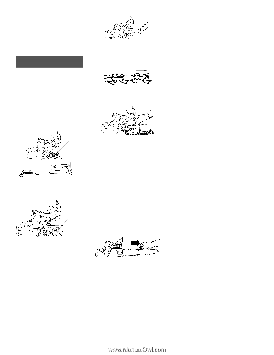
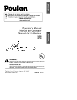
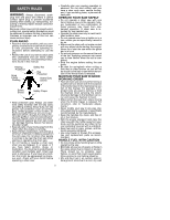
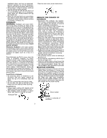
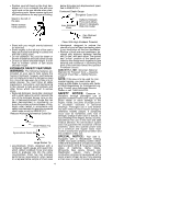
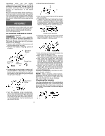
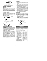
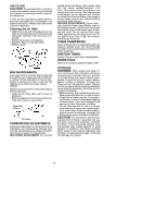
regulations exist, you are legally responsible for maintaining the operating condition of these parts. Failure to do so is a violation of the law. Refer to the SERVICE section for maintenance of the Spark Arrestor. Failure to follow all Safety Rules and Precautions can result in serious injury. If situations occur which are not covered in this manual, use care and good judgement. If you need assistance, contact your Authorized Service Dealer. ASSEMBLY The assembly tool provided with your saw is the only tool needed for assembly. Protective gloves (not provided) should be worn during assembly. ATTACHING THE BAR & CHAIN (If not already attached) WARNING: Recheck each assembly step if the saw is received assembled. Always wear gloves when handling the chain. The chain is sharp and can cut you even when it is not moving! S Loosen and remove the clamp nuts and the bar clamp from the saw. S Remove the plastic shipping spacer (if present). Shipping Spacer Assembly Tool Bar Clamp Clamp Nuts S An adjusting pin and screw is used to adjust the tension of the chain. It is very important when assembling the bar, that the pin located on the adjusting screw aligns into a hole in the bar. Adjustment Screw S Mount the bar as illustrated. S Slide the bar toward the rear of the saw as far as possible. S Prepare the chain by checking the proper direction. Without following the illustration it is easy to place the chain on the saw the wrong direction. Use the illustration of the chain to determine the proper direction. Tip of Bar Proper chain direction S Place the chain onto the sprocket located behind the clutch drum. Fit the chain between the teeth in the sprocket. S Start at the top of the bar and fit chain into groove around the guide bar. S After chain is installed, pull bar forward until chain is snug in the groove of the bar. S Hold guide bar against the saw frame making sure the adjusting pin is aligned with the hole in the bar. Remember this pin moves the bar forward and backward as screw is turned. Install the bar clamp. S Replace the bar clamp nuts and tighten finger tight. Once the chain is tensioned you will need to tighten bar clamp nuts. CHAIN TENSION (Including units with chain already installed) NOTE: When adjusting chain tension, make sure the bar nuts are finger tight only. Attempting to tension the chain when the bar nuts are tight can cause damage. Checking the tension: Use the screwdriver end of the combination screwdriver/wrench tool to move the chain around the bar. If the chain does not rotate, it is too tight. If too loose, the chain will sag below the bar. S Turn the adjusting screw counterclockwise to move the adjusting pin almost as far as it will go to the rear. This should allow the pin to be near the correct position. Further adjustment may be necessary as you mount the bar. 5
-
 1
1 -
 2
2 -
 3
3 -
 4
4 -
 5
5 -
 6
6 -
 7
7 -
 8
8 -
 9
9 -
 10
10 -
 11
11 -
12
 |
 |