Poulan 96194000801 User Manual
Poulan 96194000801 Manual
 |
View all Poulan 96194000801 manuals
Add to My Manuals
Save this manual to your list of manuals |
Poulan 96194000801 manual content summary:
- Poulan 96194000801 | User Manual - Page 1
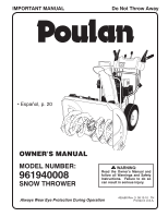
Do Not Throw Away • Español, p. 20 OWNER'S MANUAL MODEL NUMBER: 961940008 SNOW THROWER WARNING: Read the Owner's Manual and follow all Warnings and Safety Instructions. Failure to do so can result in serious injury. Always Wear Eye Protection During Operation 435580 Rev. 3 08.10.10 TH Printed - Poulan 96194000801 | User Manual - Page 2
startup. CAUTION: Muffler and other engine parts become extremely hot during operation and remain understand and follow all instructions on the machine and in the manual(s) before operating this powered equipment Vibration is generally a warning of trouble. from the truck or trailer and refuel - Poulan 96194000801 | User Manual - Page 3
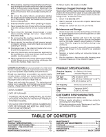
moving parts instructions under "Maintenance" and "Storage" sections of this owner's manual. TABLE OF CONTENTS SAFETY RULES 2-3 MAINTENANCE 13-14 PRODUCT SPECIFICATIONS 3 SERVICE AND ADJUSTMENTS 15-17 CUSTOMER RESPONSIBILITIES 3 STORAGE 18 ASSEMBLY / PRE-OPERATION 4-6 TROUBLESHOOTING - Poulan 96194000801 | User Manual - Page 4
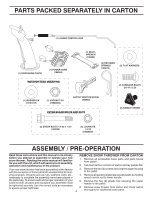
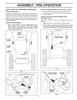
LOCKNUTS 1/4-20 (73800400) ASSEMBLY / PRE-OPERATION Read these instructions and this manual in its entirety before you attempt to assemble or operate your rod to lower handle. the parts bag. To ensure safe and proper operation of your snow thrower, all parts and hardware you assemble must 5. - Poulan 96194000801 | User Manual - Page 5
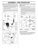
belt cover. Store the extra shear bolts, nuts and multi-wrench provided in parts bag in the toolbox. NOTE: The multi-wrench may be used for assembly securely. Additional carriage bolts, washers and handle knobs are in bag of parts. Use to secure upper handle to lower handle. Install in lower holes - Poulan 96194000801 | User Manual - Page 6
spring. CONTROL ARM AUGER CONTROL ROD VINYL SLEEVE INSTALL DISCHARGE CHUTE / CHUTE ROTATOR HEAD (See Fig. 7) NOTE: The multi-wrench provided in your parts bag may be used to install the chute rotator head. 1. Place discharge chute assembly on top of chute base with discharge opening toward front - Poulan 96194000801 | User Manual - Page 7
yourself with the location of various controls and adjustments. Save this manual for future reference. These symbols may appear on your snow READ AND FOLLOW ALL SAFETY INFORMATION AND INSTRUCTIONS BEFORE USE OF THIS PRODUCT. KEEP THESE INSTRUCTIONS FOR FUTURE REFERENCE. IGNITION KEY. INSERT - Poulan 96194000801 | User Manual - Page 8
MUFFLER GASOLINE FILLER CAP CHOKE CONTROL SAFETY IGNITION KEY ON / OFF SWITCH PRIMER FUEL SHUT-OFF VALVE RECOIL (AUXILIARY) STARTER HANDLE NOTE: ITEMS ABOVE ARE SHOWN IN THEIR TYPICAL LOCATION ON THE ENGINE. ACTUAL LOCATION MAY VARY WITH THE ENGINE ON YOUR UNIT. OPERATION ELECTRIC START BUTTON - Poulan 96194000801 | User Manual - Page 9
DISCHARGE (See Figs. 11 & 12) WARNING: Snow throwers have exposed rotating parts, which can cause severe injury from contact, or from material thrown from the chute or auger become clogged, shut-off engine and wait for all moving parts to stop. Use the clean-out tool, NOT YOUR HANDS, to unclog the - Poulan 96194000801 | User Manual - Page 10
tool to dislodge this blockage. When cleaning, repairing, or inspecting, make certain all controls are disengaged and the auger/impeller and all moving parts have stopped. Disconnect the spark plug wire and keep the wire away from the spark plug to prevent accidental starting. • Release the auger - Poulan 96194000801 | User Manual - Page 11
wait for all moving parts to stop. 2. Adjust reversed, providing additional service before requiring replacement. Replace in the Maintenance section of this manual. ADD GASOLINE (See Fig. 17) . To avoid engine problems, the fuel system season. See Storage Instructions for additional information. - Poulan 96194000801 | User Manual - Page 12
downwind whenever possible. • Adjust the skid plates to proper height for current snow conditions. See "TO ADJUST SKID PLATES" in this section of this manual. • For extremely heavy snow, reduce the width of snow removal by overlapping previous path and moving slowly. • Keep engine clean and clear of - Poulan 96194000801 | User Manual - Page 13
instructed in this manual. Some adjustments will need to be made periodically to properly maintain your snow thrower. All adjustments in the Service and Adjustments section of this manual schedule in this manual. NOTE: Use only Original Equipment Manufacturer (OEM) parts to service this unit. Failure - Poulan 96194000801 | User Manual - Page 14
(if removed for draining oil). Be sure to install klik pin into proper hole in wheel axle (See "TO REMOVE WHEELS" in the Service and Adjustments section of this manual). 7. Remove oil fill cap/dipstick. Be careful not to allow dirt to enter the engine. 8. Refill engine with oil through oil dipstick - Poulan 96194000801 | User Manual - Page 15
service or adjustments: 1. Be sure the on/off switch is in the OFF position. 2. Remove safety ignition key. 3. Make sure the augers and all moving parts discharged, see "TO CONTROL SNOW DISCHARGE" in the Operation section of this manual. SHEAR BOLTS (See Fig. 18) AUGER SHEAR BOLTS Both right and left - Poulan 96194000801 | User Manual - Page 16
should be replaced. It is recommended that the belt(s) be replaced by a service center/department. NOTE: It is recommended that both the auger and traction drive COVER - See "TO REMOVE BELT COVER" in this section of this manual. 4. REMOVE ENGINE PULLEY - Remove bolt, flat washer securing pulley to - Poulan 96194000801 | User Manual - Page 17
tire sealant may be purchased from your local parts dealer. Tire sealant also prevents tire dry rot and until cable is snug. ENGINE See engine manual. CARBURETOR Your carburetor is not adjustable. to suspected carburetor problems, take your snow thrower to a qualified service center. ENGINE - Poulan 96194000801 | User Manual - Page 18
Service and Adjustments section of this manual). 3. Lubricate as shown in the Maintenance section of this manual. 4. Be sure that all nuts, bolts, screws, and pins are securely fastened. Inspect moving parts and/or dirt in your gasoline will cause problems. • If possible, store your snow thrower - Poulan 96194000801 | User Manual - Page 19
TROUBLESHOOTING See appropriate section in manual unless directed to a qualified service center/department. PROBLEM CAUSE CORRECTION FAST position. 5. Move to FULL position. 6. Prime as instructed in the Operation section of this manual. 7. Wait a few minutes before restarting, DO NOT prime. - Poulan 96194000801 | User Manual - Page 20
REPAIR PARTS SNOW THROWER - MODEL NUMBER 96194000801 AUGER HOUSING / IMPELLER ASSEMBLY 5 15 14 4 11 6 11 16 1 inch = 25.4 mm IMPORTANT: Use only Original Equipment Manufacturer (O.E.M.) replacement parts. Failure to do so could be hazardous, damage your snow thrower and void your warranty. 38 - Poulan 96194000801 | User Manual - Page 21
25 26 27 28 29 30 31 32 33 34 35 36 37 PART NO. 175321X431 427148 188909 427146 175322 178675X008 192199 405400 73800400 74780426 427942 25.4 mm IMPORTANT: Use only Original Equipment Manufacturer (O.E.M.) replacement parts. Failure to do so could be hazardous, damage your snow thrower and void - Poulan 96194000801 | User Manual - Page 22
AUGER HOUSING SCRAPPER BAR CARRIAGE BOLT 5/16−18 X .625 NUT 5/16−18 3 (5x) 4 (5x) 2 01.07.001-A 2 1 01.07.017-A KEY NO. 1 2 PART NO. 420493X479 420494X479 DESCRIPTION AUGER ASSEMBLY LH 24 AUGER ASSEMBLY RH 24 NOTE: All component dimensions given in U.S. inches. 1 inch = 25.4 mm IMPORTANT: Use - Poulan 96194000801 | User Manual - Page 23
NO. 420478 411939 179582 DESCRIPTION AUGER BEARING BEARING PLUG SCREW 5/16−18 X 1.00 4 3 3 4 1 01.11.001-B 2 KEY NO. 1 2 3 4 PART NO. 174762X431 178777X431 72270506 751153 DESCRIPTION SKID PLATE LH SKID PLATE RH CARRIAGE BOLT 5/16−18 X .75 NUT 5/16−18 NOTE: All component dimensions given - Poulan 96194000801 | User Manual - Page 24
PANEL / DISCHARGE CHUTE 11 2 10 5 8 3 6 9 11 6 4 11 7 1 6 13 12 01.09.005-E KEY NO. 1 2 3 4 5 6 7 8 9 10 11 12 13 PART NO. 435023X428 178633X428 420325 179096X428 189713X428 128415 185600 72270505 191730 155415 179246 430324 419822X431 DESCRIPTION CHUTE WELDMENT DEFLECTOR WELDMENT - Poulan 96194000801 | User Manual - Page 25
ASSEMBLY ADJUSTABLE CABLE ASSEMBLY HEAT SHIELD *4 01.09.010-B *5 NOTES: 1. ITEMS INDICATED WITH AN * ARE LISTED AS REFERENCE FOR SERVICE PARTS ONLY. NOTE: All component dimensions given in U.S. inches. 1 inch = 25.4 mm IMPORTANT: Use only Original Equipment Manufacturer (O.E.M.) replacement - Poulan 96194000801 | User Manual - Page 26
96194000801 10 2 11 9 5 7 6 8 47 9 1 3 13 8 01.08.002-G 13 14 12 12 14 KEY NO. 1 2 3 4 5 6 7 8 9 10 11 12 13 14 PART NO. 412683X479 424517X479 424516X479 426917X431 426918X431 412677 421613 169675 17060410 414280 414281 178899 19131316 72120618 DESCRIPTION CONTROL PANEL CONTROL LEVER LH - Poulan 96194000801 | User Manual - Page 27
7 74780524 SCREW 5/16−18 X 1.50 8 751153 NUT 5/16−18 9 155415 WASHER 01.08.003-A 1 KEY PART NO. NO. DESCRIPTION 2 4 1 419797X431 LOWER HANDLE 2 427513X431 PIVOT SUPPORT WELDMENT 3 428867 SCREW 5/16−18 X .750 4 17000616 SCREW 3/8−16 X 1.00 3 4 3 4 4 01-05-013-A NOTE: All - Poulan 96194000801 | User Manual - Page 28
4 KEY NO. 1 2 3 4 5 6 7 8 9 10 PART NO. 180480 405740 180445 187716 180447 178669 180926 72270505 155377 169675 DESCRIPTION IMPELLER 25.4 mm IMPORTANT: Use only Original Equipment Manufacturer (O.E.M.) replacement parts. Failure to do so could be hazardous, damage your snow thrower and void your - Poulan 96194000801 | User Manual - Page 29
CONSOLE PANEL HEADLIGHT BEZEL FLOOD HEADLIGHT SHOULDER SCREW 10−24 X .625 SCREW 10−24 X 1.25 WIRE HARNESS BULB 4 5 2 1 6 KEY PART NO. NO. DESCRIPTION 3 1 412675X431 INTERLOCK SPRING 2 414572 INTERLOCK CAM 3 178831 TORSION SPRING 4 169675 RETAINER 5 17060410 SCREW 1/4−20 X .625 - Poulan 96194000801 | User Manual - Page 30
REPAIR PARTS DRIVE SNOW THROWER - MODEL NUMBER 96194000801 42 EXPLODED 2 16 1 17 15 14 15 12 9 11 inches. 1 inch = 25.4 mm IMPORTANT: Use only Original Equipment Manufacturer (O.E.M.) replacement parts. Failure to do so could be hazardous, damage your snow thrower and void your warranty. 48 - Poulan 96194000801 | User Manual - Page 31
12 13 14 15 16 17 18 19 20 21 22 23 24 25 26 PART NO. 198875 17501010 402685X428 17490508 57079 405485 198580 403097X431 402881 403096X431 191730 402856X431 416717X431 42 43 44 45 46 47 48 49 50 51 52 53 PART NO. 179831 175344 178613 74760514 12000012 402187 401619 417234 401984X431 180135 402652 - Poulan 96194000801 | User Manual - Page 32
DRIVE SNOW THROWER - MODEL NUMBER 96194000801 7 1b 6 6 1b 1a 5 4 3 2 3 5 4 01.03.005-B KEY NO. 1 1a 1b 2 3 4 5 6 7 PART NO. 188226 179352 9465M1 402691 174697 179830 17490508 155443 189282 DESCRIPTION (assy of 1a,1b) AXLE ASSEMBLY AXLE SHAFT ROLL PIN 3/16 SPROCKET THRUST WASHER - Poulan 96194000801 | User Manual - Page 33
150406 428867 DESCRIPTION COMPLETE LCT ENGINE FRAME BOLT 3/8-16 SCREW 5/16-18 X .750 KEY NO. 1 PART NO. 427963X428 DESCRIPTION ENGINE MOUNTING PLATE 01.01.004-A 1 KEY NO. 1 PART NO. 428684 DESCRIPTION COVER ASSEMBLY 01.21.013-B NOTE: All component dimensions given in U.S. inches. 1 inch - Poulan 96194000801 | User Manual - Page 34
NO. 13 14 15 16 17 18 19 20 21 22 23 24 PART NO. 74780520 59289 73800500 851084 400026 426491 426490 74610516 10040500 155452 11050500 175331 PULLEY ENG TRACTION SCREW 5/16-18 X 1 .00 LOCKWASHER 5/16 BELT GUIDE LOCKWASHER 5/16 IDLER BUSHING NOTE: All component dimensions given in U.S. inches - Poulan 96194000801 | User Manual - Page 35
432332X417 DESCRIPTION WHEEL ASSEMBLY LH WHEEL ASSEMBLY RH NOTE: All component dimensions given in U.S. inches. 1 inch = 25.4 mm IMPORTANT: Use only Original Equipment Manufacturer (O.E.M.) replacement parts. Failure to do so could be hazardous, damage your snow thrower and void your warranty. 53 - Poulan 96194000801 | User Manual - Page 36
CARRIAGE BOLT 5/16-18 X .75 NUT 5/16-18 NOTE: All component dimensions given in U.S. inches. 1 inch = 25.4 mm IMPORTANT: Use only Original Equipment Manufacturer (O.E.M.) replacement parts. Failure to do so could be hazardous, damage your snow thrower and void your warranty. 54 - Poulan 96194000801 | User Manual - Page 37
MODEL NUMBER 96194000801 1 4 9 6 7 1 3 KEY NO. 1 3 4 6 7 9 - - PART NO. 181037 181035 181042 181033 428716 429591 435580 DESCRIPTION DECAL, DANGER DECAL, DANGER, DEFLECTOR DECAL, DANGER DECAL, INSTRUCTION DECAL, TRACTION LEVER DECAL, SPEED CONTROL OWNER'S MANUAL, ENGLISH / SPANISH NOTE: All - Poulan 96194000801 | User Manual - Page 38
charge for parts or labor incurred in replacing parts, any part which be maintained in accordance with the instructions furnished. 4. The Warranty period for service dealer. Should you have any unanswered questions concerning this Warranty, please contact: HOP Outdoor Products Customer Service
-
 1
1 -
 2
2 -
 3
3 -
 4
4 -
 5
5 -
 6
6 -
 7
7 -
8
-
9
-
10
-
11
-
12
-
13
-
14
-
15
-
16
-
17
-
18
-
19
-
20
-
21
-
22
-
23
-
24
-
25
-
26
-
27
-
28
-
29
-
30
-
31
-
32
-
33
-
34
-
35
-
36
-
37
-
38
 |
 |
OWNER'S MANUAL
MODEL NUMBER:
961940008
SNOW THROWER
Always Wear Eye Protection During Operation
IMPORTANT MANUAL
Do Not Throw Away
WARNING:
Read the Owner's Manual and
follow all Warnings and Safety
Instructions.
Failure to do so
can result in serious injury.
435580 Rev. 3
08.10.10
TH
Printed in U.S.A.
• Español, p. 20