Poulan 96194000801 User Manual - Page 4
Assembly
 |
View all Poulan 96194000801 manuals
Add to My Manuals
Save this manual to your list of manuals |
Page 4 highlights
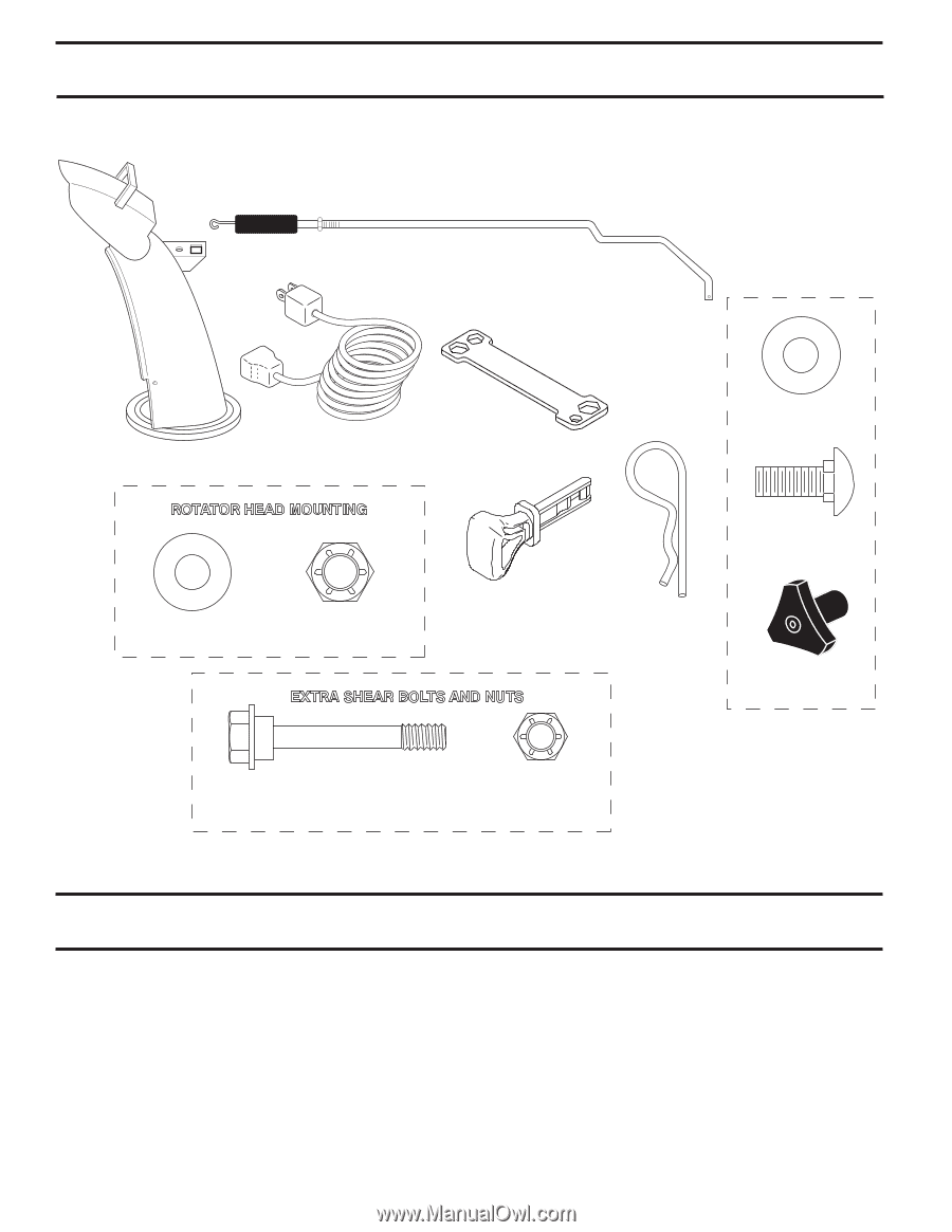
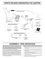
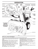
PARTS PACKED SEPARATELY IN CARTON (1) AUGER CONTROL ROD (1) DISCHARGE CHUTE (1) POWER CORD (198563) ROTATOR HEAD MOUNTING (1) MULTIWRENCH (180684) (3) RETAINER SPRINGS (169675) (2) FLAT WASHERS (2) CARRIAGE BOLTS 3/8-16 x 2.25 (1) WASHER 3/8 (19131316) (1) LOCKNUT 3/8 (73800600) SAFTEY IGNITION KEY(S) (422663) EXTRA SHEAR BOLTS AND NUTS (2) HANDLE KNOBS (2) SHEAR BOLTS 1/4-20 x 1-3/4 (192090) (2) LOCKNUTS 1/4-20 (73800400) ASSEMBLY / PRE-OPERATION Read these instructions and this manual in its entirety before you attempt to assemble or operate your new snow thrower. Reading the entire manual will familiarize you with the unit, which will assist you in assembly, operation and maintenance of the product. REMOVE SNOW THROWER FROM CARTON 1. Remove all accessible loose parts and parts boxes from carton. 2. Cut down all four corners of carton and lay panels flat. Your new snow thrower has been assembled at the factory with the exception of those parts left unassembled for ship- 3. Remove the two (2) screws securing the auger housing to the pallet. ping purposes. All parts such as nuts, washers, bolts, etc., 4. Remove all packing materials except plastic tie holding necessary to complete the assembly have been placed in speed control rod to lower handle. the parts bag. To ensure safe and proper operation of your snow thrower, all parts and hardware you assemble must 5. Remove the two (2) plastic ties securing the upper handle to the pallet. be tightened securely. Use the correct tools as necessary to ensure proper tightness. 4 6. Remove snow thrower from carton and check carton thoroughly for additional loose parts.
-
 1
1 -
 2
2 -
 3
3 -
 4
4 -
 5
5 -
 6
6 -
 7
7 -
 8
8 -
 9
9 -
 10
10 -
11
-
12
-
13
-
14
-
15
-
16
-
17
-
18
-
19
-
20
-
21
-
22
-
23
-
24
-
25
-
26
-
27
-
28
-
29
-
30
-
31
-
32
-
33
-
34
-
35
-
36
-
37
-
38
 |
 |